Machine-Level Representation of Programs
In this chapter, we will take a close look at machine code and its human-readable representation as assembly code.
Best of all, a program written in a high-level language can be compiled and executed on a number of different machines, whereas assembly code is highly machine specific.
Our presentation is based on x86-64, the machine language for most of the processors found in today’s laptop and desktop machines, as well as those that power very large data centers and supercomputers.
3.1 A Historical Perspective
The Intel processor line, colloquially referred to as x86, has followed a long evolutionary development.
It started with one of the first single-chip 16-bit microprocessors, where many compromises had to be made due to the limited capabilities of integrated circuit technology at the time.
Since then, it has grown to take advantage of technology improvements as well as to satisfy the demands for higher performance and for supporting more advanced operating systems.
8086(1978, 29 K transistors).One of the first single-chip, 16-bit microprocessors. The 8088, a variant of the 8086 with an 8-bit external bus, formed the heart of the original IBM personal computers. IBM contracted with then-tiny Microsoft to develop the MS-DOS operating system. The original models came with 32,768 bytes of memory and two floppy drives (no hard drive). Architecturally, the machines were limited to a 655,360-byte address space—addresses were only 20 bits long (1,048,576 bytes addressable), and the operating system reserved 393,216 bytes for its own use. In 1980, Intel introduced the 8087 floating-point coprocessor (45 K transistors) to operate alongside an 8086 or 8088 processor, executing the floating-point instructions. The 8087 established the floating-point model for the x86 line, often referred to as “x87.”
80286(1982, 134 K transistors).Added more (and now obsolete) addressing modes. Formed the basis of the IBM PC-AT personal computer, the original platform for MS Windows.
i386(1985, 275 K transistors).Expanded the architecture to 32 bits. Added the flat addressing model used by Linux and recent versions of the Windows operating system. This was the first machine in the series that could fully support a Unix operating system
i486(1989, 1.2 M transistors).Improved performance and integrated the floating-point unit onto the processor chip but did not significantly change the instruction set.
Pentium(1993, 3.1 M transistors).Improved performance but only added minor extensions to the instruction set.
PentiumPro(1995, 5.5 M transistors).Introduced a radically new processor design, internally known as the P6 microarchitecture. Added a class of “conditional move” instructions to the instruction set.
Pentium/MMX(1997, 4.5 M transistors).Added new class of instructions to the Pentium processor for manipulating vectors of integers. Each datum can be 1, 2, or 4 bytes long. Each vector totals 64 bits.
Pentium II(1997, 7 M transistors).Continuation of the P6 microarchitecture.
Pentium III(1999, 8.2 M transistors).Introduced SSE, a class of instructions for manipulating vectors of integer or floating-point data. Each datum can be 1, 2, or 4 bytes, packed into vectors of 128 bits. Later versions of this chip went up to 24 M transistors, due to the incorporation of the level-2 cache on chip.
Pentium 4(2000, 42 M transistors).Extended SSE to SSE2, adding new data types (including double-precision floating point), along with 144 new instructions for these formats. With these extensions, compilers can use SSE instructions, rather than x87 instructions, to compile floating-point code
Pentium 4E(2004, 125 M transistors).Added hyperthreading, a method to run two programs simultaneously on a single processor, as well as EM64T, Intel’s implementation of a 64-bit extension to IA32 developed by Advanced Micro Devices (AMD), which we refer to as x86-64.
Core 2(2006, 291 M transistors).Returned to a microarchitecture similar to P6. First multi-core Intel microprocessor, where multiple processors are implemented on a single chip. Did not support hyperthreading.
Core i7, Nehalem(2008, 781 M transistors).Incorporated both hyperthreading and multi-core, with the initial version supporting two executing programs on each core and up to four cores on each chip.
Core i7, Sandy Bridge(2011, 1.17 G transistors).Introduced AVX, an extension of the SSE to support data packed into 256-bit vectors.
Core i7, Haswell(2013, 1.4 G transistors).Extended AVX to AVX2, adding more instructions and instruction formats.
Each successive processor has been designed to be backward compatible— able to run code compiled for any earlier version.
Intel has had several names for their processor line, including IA32, for “Intel Architecture 32-bit” and most recently Intel64, the 64-bit extension to IA32, which we will refer to as x86-64.
The memory model provided in the original 8086 and its extensions in the 80286 became obsolete with the i386. The original x87 floating-point instructions became obsolete with the introduction of SSE2.
3.2 Program Encodings
Suppose we write a C program as two files p1.c and p2.c. We can then compile this code using a Unix command line:
1 | linux> gcc -Og -o p p1.c p2.c |
- The command-line option
-Oginstructs the compiler to apply a level of optimization that yields machine code that follows the overall structure of the original C code. - Invoking higher levels of optimization can generate code that is so heavily transformed that the relationship between the generated machine code and the original source code is difficult to understand.
- We will therefore use
-Ogoptimization as a learning tool and then see what happens as we increase the level of optimization. In practice, higher levels of optimization (e.g., specified with the option-O1or-O2) are considered a better choice in terms of the resulting program performance.
3.2.1 Machine-Level Code
In the abstract model of computer, two of these are especially important for machine-level programming.
- First, the format and behavior of a machine-level program is defined by the instruction set architecture, or ISA, defining the processor state, the format of the instructions, and the effect each of these instructions will have on the state.
- Second, the memory addresses used by a machine-level program are virtual addresses, providing a memory model that appears to be a very large byte array
Being able to understand assembly code and how it relates to the original C code is a key step in understanding how computers execute programs.
The machine code for x86-64 differs greatly from the original C code. Parts of the processor state are visible that normally are hidden from the C programmer:
The program counter (commonly referred to as the PC, and called
%ripin x86- 64) indicates the address in memory of the next instruction to be executed.The integer register file contains 16 named locations storing 64-bit values.
These registers can hold addresses (corresponding to C pointers) or integer data. Some registers are used to keep track of critical parts of the program state, while others are used to hold temporary data, such as the arguments and local variables of a procedure, as well as the value to be returned by a function.
The condition code registers hold status information about the most recently executed arithmetic or logical instruction.
These are used to implement conditional changes in the control or data flow, such as is required to implement
ifandwhilestatements.A set of vector registers can each hold one or more integer or floating-point values.
Whereas C provides a model in which objects of different data types can be declared and allocated in memory, machine code views the memory as simply a large byte-addressable array
Aggregate data types in C such as arrays and structures are represented in machine code as contiguous collections of bytes.
Even for scalar data types, assembly code makes no distinctions between signed or unsigned integers, between different types of pointers, or even between pointers and integers.
(No “type” here !)
As mentioned earlier, the program memory is addressed using virtual addresses.
At any given time, only limited subranges of virtual addresses are considered valid.
For example, x86-64 virtual addresses are represented by 64-bit words. In current implementations of these machines, the upper 16 bits must be set to zero, and so an address can potentially specify a byte over a range of $2^{48}$, or 64 terabytes.
The operating system manages this virtual address space, translating virtual addresses into the physical addresses of values in the actual processor memory.
The compiler must generate sequences of instructions to implement program constructs such as arithmetic expression evaluation, loops, or procedure calls and returns.
The opensource community supporting gcc keeps changing the code generator, attempting to generate more efficient code according to changing code guidelines provided by the microprocessor manufacturers.
Our goal in studying the examples shown in our presentation is to demonstrate how to examine assembly code and map it back to the constructs found in high-level programming languages. You will need to adapt these techniques to the style of code generated by your particular compiler.
3.2.2 Code Examples
Suppose we write a C code file mstore.c containing the following function definition:
1 | long mult2(long, long); |
To see the assembly code generated by the C compiler
1 | $ gcc -Og -S mstore.c |
-S will cause gcc to run the compiler, generating an assembly file mstore.s, and go no further.
The assembly-code file contains various declarations, including the following set of lines:
1 | multstore: |
Each indented line in the code corresponds to a single machine instruction.
All information about local variable names or data types has been stripped away.
If we use the -c command-line option, gcc will both compile and assemble the code
1 | $ gcc -Og -c mstore.c |
This will give us a binary file mstore.o
Embedded within the 1,368 bytes of the file mstore.o is a 14-byte sequence with the hexadecimal representation
1 | $ hexdump -C mstore.o | grep '53 48 89 d3 e8 00 00 00 00 48 89 03 5b c3' |
This is the object code corresponding to the assembly instructions listed previously
A key lesson to learn from this is that the program executed by the machine is simply a sequence of bytes encoding a series of instructions. The machine has very little information about the source code from which these instructions were generated.
Programs call disassembler generate a format similar to assembly code from the machine code.
1 | $ objdump -d mstore.o |
1 | mstore.o: file format elf64-x86-64 |
Several features about machine code and its disassembled representation are worth noting:
x86-64instructions can range in length from 1 to 15 bytes. The instruction encoding is designed so that commonly used instructions and those with fewer operands require a smaller number of bytes than do less common ones or ones with more operands.The instruction format is designed in such a way that from a given starting position, there is a unique decoding of the bytes into machine instructions. For example, only the instruction
pushq %rbxcan start with byte value 53.The disassembler determines the assembly code based purely on the byte sequences in the machine-code file. It does not require access to the source or assembly-code versions of the program.
The disassembler uses a slightly different naming convention for the instructions than does the assembly code generated by
gcc.In our example, it has omitted the suffix
qfrom many of the instructions. These suffixes are size designators and can be omitted in most cases. Conversely, the disassembler adds the suffixqto the call and ret instructions. Again, these suffixes can safely be omitted.
Generating the actual executable code requires running a linker on the set of object-code files, one of which must contain a function main.
1 | //source of main.c |
1 | $ gcc -Og -o prog main.c mstore.c |
The file prog has grown to 8,655 bytes, since it contains not just the machine code for the procedures we provided but also code used to start and terminate the program as well as to interact with the operating system.
We can disassemble the file prog:
1 | $ objdump -d prog |
1 | prog: file format elf64-x86-64 |
Note that this the codes of multstore hold.
1 | 0000000000000741 <multstore>: |
One important difference is that the addresses listed along the left are different— the linker has shifted the location of this code to a different range of addresses.
A second difference is that the linker has filled in the address that the
callqinstruction should use in calling the functionmult2. One task for the linker is to match function calls with the locations of the executable code for those functions.A final difference is that we see one additional lines of code
nop. This instruction will have no effect on the program, since it occurs after the return instruction.It has been inserted to grow the code, enabling a better placement of the next block of code in terms of memory system performance.
3.2.3 Notes on Formatting
The assembly code generated by gcc contains information with which we need not be concerned and does not provide any description of the program or how it works.
1 | $ cat mstore.s |
1 | .file "mstore.c" |
All of the lines beginning with ‘.’ are directives to guide the assembler and linker. We can generally ignore these.
We will do two main task:
omits most of the directives which begin with ‘.’
1
2
3
4
5
6
7
8
9
10
11
12
13#!/usr/bin/python3
# source of wash.py
import sys
clothes = sys.argv[1]
f = open(clothes , 'rt')
after = open('clean_' + clothes , 'wt' )
ls = []
for line in f:
if line.strip()[0] != '.' or len(line.strip()) == 4 :
ls.append(line)
after.writelines(ls)
f.close()
after.close()add some annotation(Unfortunately, this can only be done manually)
1 | #void multstore(long x, long y, long *dest) |
1 | ; intel format |
Difference between ATT format and intel format
ATT(name after AT&T) fomat is the default format for gcc, objdump, and the other tools we will consider.
intel format is from Microsoft, it can be shown by telling
gcc-masm=intel
- The Intel code omits the size designation suffixes. We see instruction
pushandmovinstead ofpushqandmovq.- The Intel code omits the
%character in front of register names, usingrbxinstead of%rbx- The Intel code has a different way of describing locations in memory—for example,
QWORD PTR [rbx]rather than(%rbx).- Instructions with multiple operands list them in the reverse order. This can be very confusing when switching between the two formats!!!
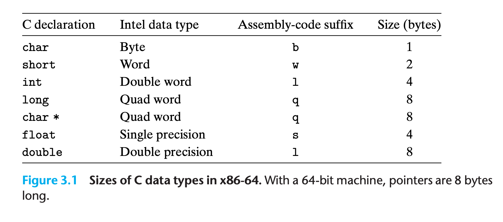
3.3 Data Formats
Intel uses the term “word” to refer to a 16-bit data type. Based on this, they refer to 32- bit quantities as “double words,” and 64-bit quantities as “quad words.”
Microprocessors in the x86 family historically implemented all floating-point operations with a special 80-bit floating-point format. This format can be specified in C programs using the declaration long double.
We recommend against using this format, however.
- It is not portable to other classes of machines
- it is typically not implemented with the same high-performance hardware as is the case for single- and double-precision arithmetic.
most assembly-code instructions generated by gcc have a single-character suffix denoting the size of the operand.
For example, the data movement instruction has four variants:
movb(move byte),movw(move word),movl(move double word), andmovq(move quad word).- The suffix ‘l’ is used for double words, since 32-bit quantities are considered to be “long words.”
The assembly code uses the suffix l to denote a 4-byte integer as well as an 8-byte double-precision floating-point number. This causes no ambiguity, since floating-point code involves an entirely different set of instructions and registers.
3.4 Accessing Information
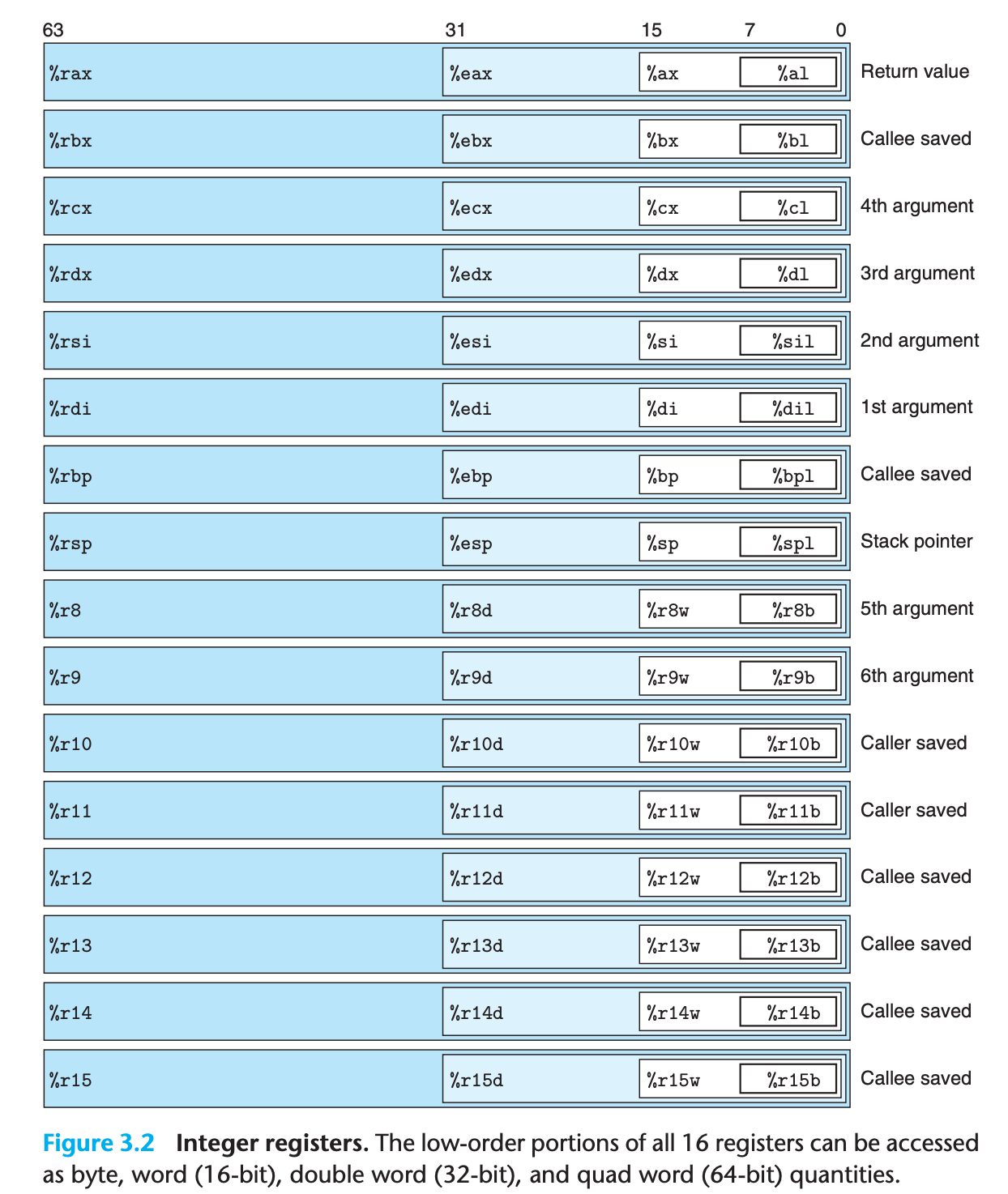
An x86-64 central processing unit (CPU) contains a set of 16 general-purpose registers storing 64-bit values.
Their names all begin with
%r(short for register), but otherwise follow multiple different naming conventions, owing to the historical evolution of the instruction set.The original 8086 had eight 16-bit registers. Each had a specific purpose, and hence they were given names that reflected how they were to be used.
With the extension to IA32, these registers were expanded to 32-bit registers, labeled
%eaxthrough%ebp(short for extended).In the extension to x86-64, the original eight registers were expanded to 64 bits, labeled
%raxthrough%rbp.In addition, eight new registers were added, and these were given labels according to a new naming convention:
%r8through%r15
instructions can operate on data of different sizes stored in the low-order bytes of the 16 registers.
- Byte-level operations can access the least significant byte, 16-bit operations can access the least significant 2 bytes, 32-bit operations can access the least significant 4 bytes, and 64-bit operations can access entire registers.
When instructions for copying and generating 1-, 2-, 4-, and 8-byte values have registers as destinations, two conventions arise for what happens to the remaining bytes in the register for instructions that generate less than 8 bytes:
- Those that generate 1- or 2-byte quantities leave the remaining bytes unchanged.
- Those that generate 4- byte quantities set the upper 4 bytes of the register to zero.
- The latter convention was adopted as part of the expansion from
IA32tox86-64
3.4.1 Operand Specifiers
Most instructions have one or more operands specifying the source values to use in performing an operation and the destination location into which to place the result
Source values can be given as constants or read from registers or memory.
Results can be stored in either registers or memory.
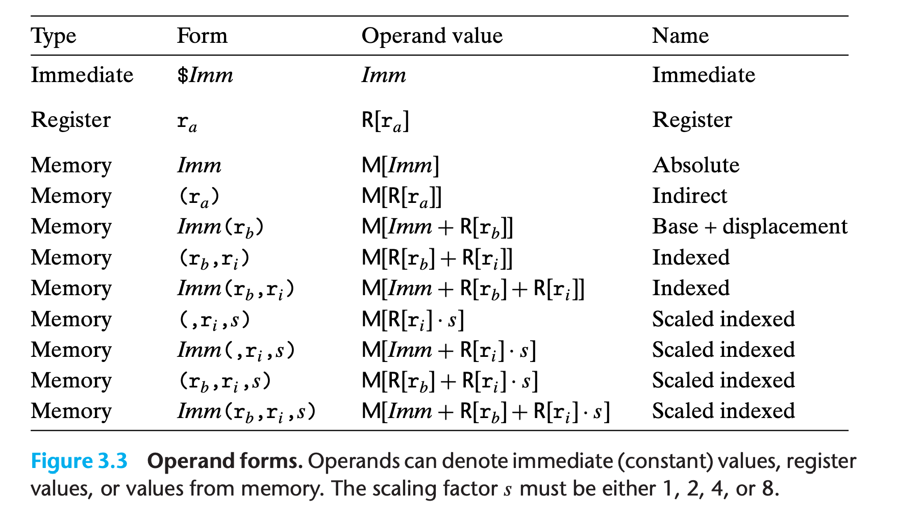
The first type, immediate, is for constant values.
- In ATTformat assembly code, these are written with a
$followed by an integer using standard C notation—for example,$-577or$0x1F. - Different instructions allow different ranges of immediate values.
- The assembler will automatically select the most compact way of encoding a value
- In ATTformat assembly code, these are written with a
The second type, register, denotes the contents of a register, one of the sixteen 8-, 4-, 2-, or 1-byte low-order portions of the registers for operands having 64, 32, 16, or 8 bits, respectively.
- we use the notation $r_a$ to denote an arbitrary register a and indicate its value with the reference R[$r_a$], viewing the set of registers as an array R indexed by register identifiers.
The third type of operand is a memory reference, in which we access some memory location according to a computed address, often called the effective address.
Since we view the memory as a large array of bytes, we use the notation $M_b[Addr]$ to denote a reference to the b-byte value stored in memory starting at address $Addr$. To simplify things, we will generally drop the subscript $b$.
There are many different addressing modes allowing different forms of memory references. The most general form is shown at the bottom of the table with syntax $Imm(r_b,r_i,s)$.
Such a reference has four components: an immediate offset $Imm$, a base register $r_b$, an index register $r_i$, and a scale factor s, where s must be 1, 2, 4, or 8. Both the base and index must be 64-bit registers.
The effective address is computed as $Imm + R[r_b] + R[r_i] \cdot s$.
This general form is often seen when referencing elements of arrays.
The other forms are simply special cases of this general form where some of the components are omitted.
the more complex addressing modes are useful when referencing array and structure elements.
Practice Problem 3.1
Assume the following values are stored at the indicated memory addresses and registers:
Address Value Register Value 0x100 0xFF %rax 0x100 0x104 0xAB %rcx 0x1 0x108 0x13 %rdx 0x3 0x10C 0x11 Fill in the following table showing the values for the indicated operands:
Operand Value %rax 0x104 $0x108 (%rax) 4(%rax) 9(%rax,%rdx) 260(%rcx , %rdx) 0xFC(,%rcx,4) (%rax,%rdx,4)
My solution: :white_check_mark:
| Operand | Value |
|---|---|
| %rax | 0x100 |
| 0x104 | 0xAB |
| $0x108 | 0x108 |
| (%rax) | 0xFF |
| 4(%rax) | 0xAB |
| 9(%rax,%rdx) | 0x11 |
| 260(%rcx , %rdx) | 0x13 |
| 0xFC(,%rcx,4) | 0xFF |
| (%rax,%rdx,4) | 0x11 |
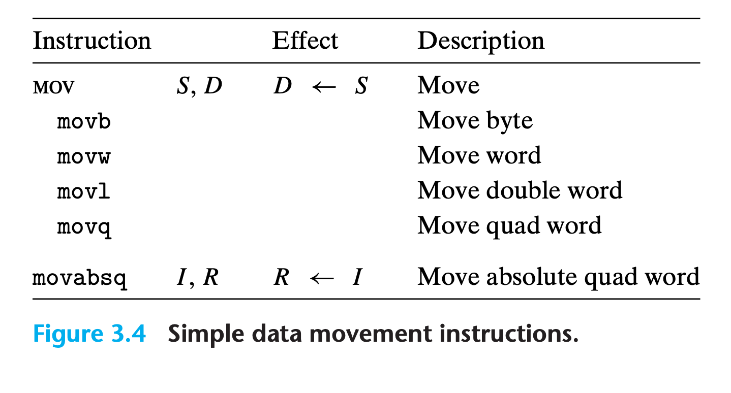
3.4.2 Data Movement Instructions
Among the most heavily used instructions are those that copy data from one location to another.
In our presentation, we group the many different instructions into instruction classes, where the instructions in a class perform the same operation but with different operand sizes.
mov class
These instructions copy data from a source location to a destination location, without any transformation.
x86-64imposes the restriction that a move instruction cannot have both operands refer to memory locations.- Copying a value from one memory location to another requires two instructions—the first to load the source value into a register, and the second to write this register value to the destination.
For most cases, the
movinstructions will only update the specific register bytes or memory locations indicated by the destination operand.The only exception is that when
movlhas a register as the destination, it will also set the high-order 4 bytes of the register to 0.
Examples
1 | movl $0x4050,%eax Immediate--Register, 4 bytes |
The regular movq instruction can only have immediate source operands that can be represented as 32-bit two’s-complement numbers. This value is then sign extended to produce the 64-bit value for the destination.
The movabsq instruction can have an arbitrary 64-bit immediate value as its source operand and can only have a register as a destination
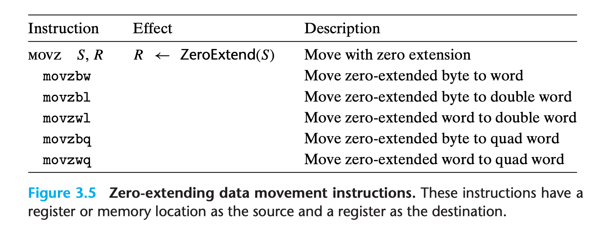
movz and movs classes
when copying a smaller source value to a larger destination.
Instructions in the
movzclass fill out the remaining bytes of the destination with zeros, while those in themovsclass fill them out by sign extension, replicating copies of the most significant bit of the source operand.Each instruction name has size designators as its final two characters—the first specifying the source size, and the second specifying the destination size.
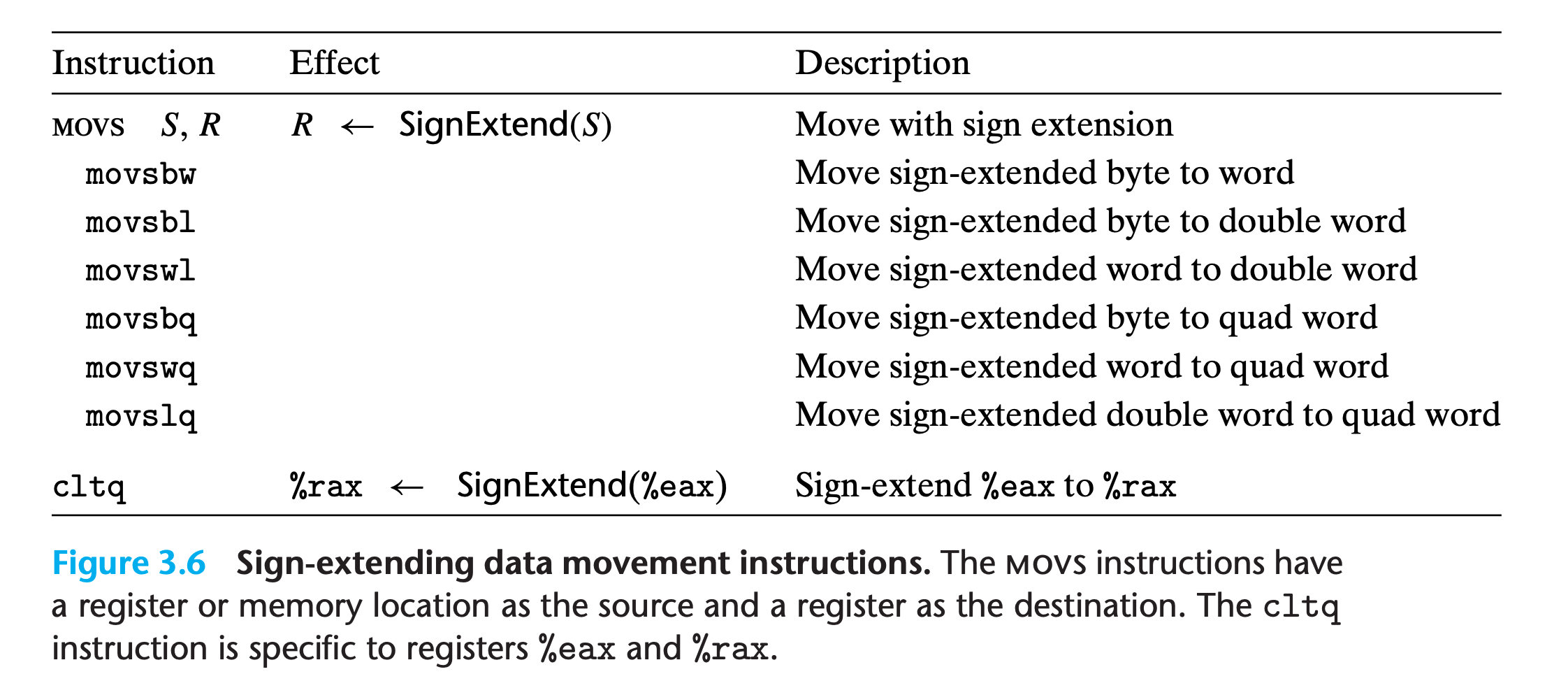
Note the absence of an explicit instruction to zero-extend a 4-byte source value to an 8-byte destination can be implemented using a
movlinstruction having a register as the destination, logically if there do exist one, it should be namedmovzlqThis technique takes advantage of the property that an instruction generating a 4-byte value with a register as the destination will fill the upper 4 bytes with zeros.
cltqstands for “convert long to quad”, in intel style this will becdqe(convert double to quad extend), it has the exact same effect as the instructionmovslq %eax, %rax, but it has a more compact encoding.
Practice Problem 3.2
For each of the following lines of assembly language, determine the appropriate instruction suffix based on the operands. (For example,
movcan be rewritten asmovb, movw, movl, ormovq.)
2
3
4
5
6
mov (%rax), %dx
mov $0xFF, %bl
mov (%rsp,%rdx,4), %dl
mov (%rdx), %rax
mov %dx, (%rax)
My solution: :white_check_mark:
1 | movl %eax, (%rsp) |
Practice Problem 3.3
Each of the following lines of code generates an error message when we invoke the assembler. Explain what is wrong with each line.
2
3
4
5
6
7
movl %rax, (%rsp)
movw (%rax),4(%rsp)
movb %al,%sl
movq %rax,$0x123
movl %eax,%rdx
movb %si, 8(%rbp)
My solution : :white_check_mark:
1 | movb $0xF, (%ebx) ;in x86_64 address should always be 64 bits, %ebx is 32 bits |
3.4.3 Data Movement Example
As an example of code that uses data movement instructions, consider the data exchange routine shown in below
1 | long exchange(long *xp, long y) |
1 | ; long exchange(long *xp, long y) |
- First, we see that what we call “pointers” in C are simply addresses. Dereferencing a pointer involves copying that pointer into a register, and then using this register in a memory reference.
- Second, local variables such as x are often kept in registers rather than stored in memory locations. Register access is much faster than memory access.
Practice Problem 3.4
Assume variables sp and dp are declared with types
2
dest_t *dp;where
src_tanddest_tare data types declared withtypedef. We wish to use the appropriate pair of data movement instructions to implement the operation
Assume that the values of
spanddpare stored in registers%rdiand%rsi, respectively.For each entry in the table, show the two instructions that implement the specified data movement.
The first instruction in the sequence should read from memory, do the appropriate conversion, and set the appropriate portion of register
%rax.The second instruction should then write the appropriate portion of
%raxto memory. In both cases, the portions may be%rax, %eax, %ax, or%al, and they may differ from one another.Recall that when performing a cast that involves both a size change and a change of “signedness” in C, the operation should change the size first
2
3
4
5
6
7
8
9
10
11
12
13
14
long long movq (%rdi), %rax
movq %rax, (%rsi)
char int
char unsigned
unsigned char long
int char
unsigned unsigned char
char short
My solution : :white_check_mark:
1 | src_t dest_t Instruction |
Practice Problem 3.5
You are given the following information. A function with prototype
is compiled into assembly code, yielding the following:
2
3
4
5
6
7
8
9
10
;xp in %rdi, yp in %rsi, zp in %rdx
decode1:
movq (%rdi), %r8
movq (%rsi), %rcx
movq (%rdx), %rax
movq %r8, (%rsi)
movq %rcx, (%rdx)
movq %rax, (%rdi)
retParameters
xp,yp, andzpare stored in registers%rdi,%rsi, and%rdx, respectively.Write C code for
decode1that will have an effect equivalent to the assembly code shown.
My solution :
1 | ; %rdi = xp |
1 | void decode1(long *xp, long *yp, long *zp){ |
Verification: :white_check_mark:
1 | $ gcc -Og -S decode.c && ./wash.py decode.s && cat clean_decode.s |
1 | decode1: |
1 | $ gcc -Og -S decode2.c && ./wash.py decode2.s && cat clean_decode2.s |
1 | decode2: |
Although use two less variables, we still get 7 instruction, no optimization !!!
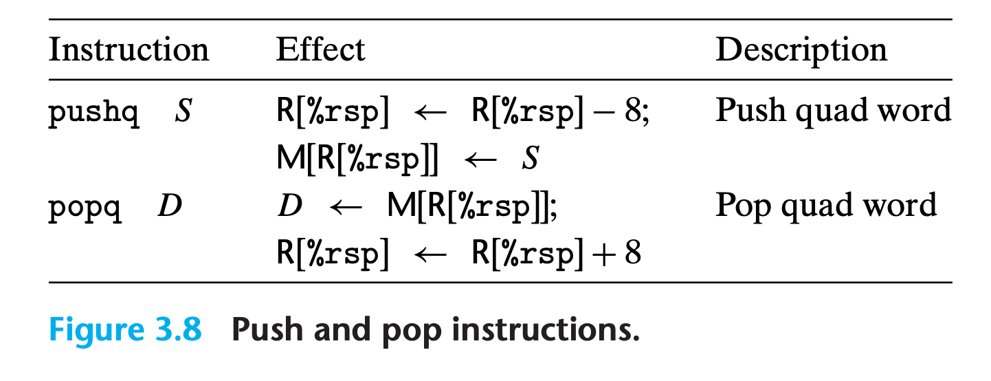
3.4.4 Pushing and Popping Stack Data
The final two data movement operations are used to push data onto and pop data from the program stack, as documented in Figure.
The stack plays a vital role in the handling of procedure calls.
With x86-64, the program stack is stored in some region of memory.
The stack grows downward such that the top element of the stack has the lowest address of all stack elements
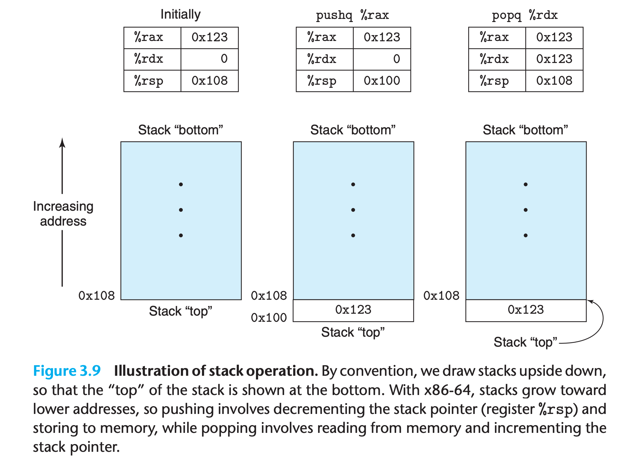
- The stack pointer
%rspholds the address of the top stack element - The
pushqinstruction provides the ability to push data onto the stack, while thepopqinstruction pops it. Each of these instructions takes a single operand—the data source for pushing and the data destination for popping.
Push
Pushing a quad word value onto the stack involves
- decrementing the stack pointer by 8
- writing the value at the new top-of-stack address.
Therefore, the behavior of the instruction pushq %rbp is equivalent to
1 | subq $8 , %rsp ;Decrement stack pointer |
The pushq instruction is encoded in the machine code as a single byte, whereas the pair of instructions shown above requires a total of 8 bytes.
Pop
Popping a quad word involves
- reading from the top-of-stack location
- incrementing the stack pointer by 8.
Therefore, the instruction popq %rax is equivalent to the following pair of instructions:
1 | movq (%rsp),%rax ;Read %rax from stack |
As shown in the figure, the ‘old’ stack top value remains in memory until it is overwritten
Stack
Since the stack is contained in the same memory as the program code and other forms of program data, programs can access arbitrary positions within the stack using the standard memory addressing methods.
3.5 Arithmetic and Logical Operations
Most of the operations are given as instruction classes, as they can have different variants with different operand sizes. Only leaq has no other size variants.(Address will always be 64 bits)
The operations are divided into four groups: load effective address, unary, binary, and shifts.
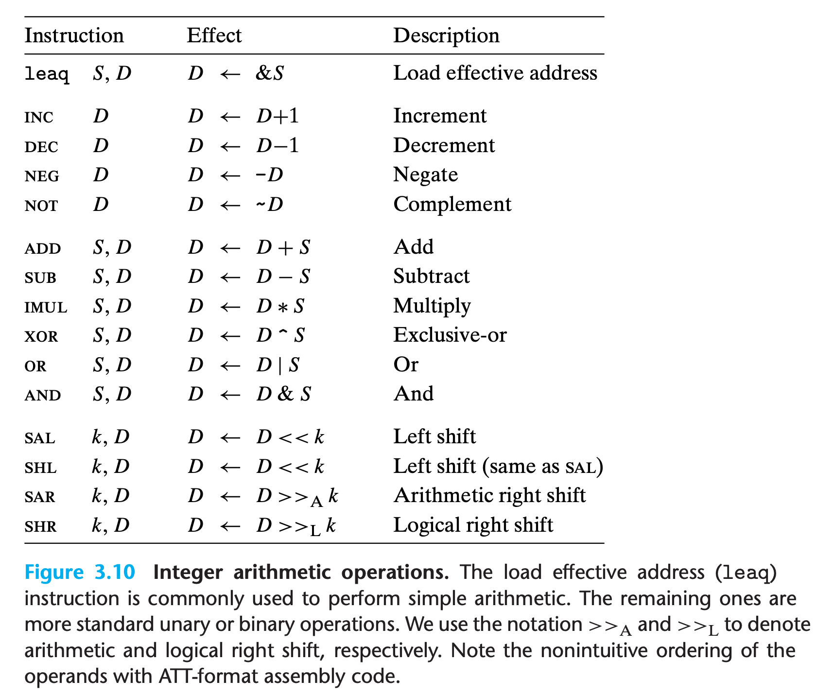
3.5.1 Load Effective Address
The load effective address instruction leaq is actually a variant of the movq instruction.
It has the form of an instruction that reads from memory to a register, but it does not reference memory at all !!!
Its first operand appears to be a memory reference, but instead of reading from the designated location, the instruction copies the effective address to the destination.
The instruction can be interpreted as C expression
1
2//leaq S,D
Type * D = &S;This instruction can be used to generate pointers for later memory references
In addition, it can be used to compactly describe common arithmetic operations, as it shown in Chapter 2
D = x << y + z- For example, if register
%rdxcontains valuex, then the instructionleaq 7(%rdx,%rdx,4), %raxwill set register %rax to5x + 7. %rax = 7 + %rdx + %rdx * 4 = 5* %rdx + 7- Compilers often find clever uses of
leaqthat have nothing to do with effective address computations.
- For example, if register
The destination operand must be a register.
Practice Problem 3.6
Suppose register
%rbxholds valuepand%rdxholds valueq. Fill in the table below with formulas indicating the value that will be stored in register%raxfor each of the given assembly-code instructions:
2
3
4
5
6
7
leaq 9(%rdx), %rax
leaq (%rdx,%rbx), %rax
leaq (%rdx,%rbx,3), %rax
leaq 2(%rbx,%rbx,7), %rax
leaq 0xE(,%rdx,3), %rax
leaq 6(%rbx,%rdx,7), %rax
My solution : :white_check_mark:
1 | #%rbx = p |
As an illustration of the use of leaq in compiled code, consider the following C program:
1 | long scale(long x, long y, long z) { |
When compiled, the arithmetic operations of the function are implemented by a sequence of three leaq functions
1 | # long scale(long x, long y, long z) |
(When compiling the codes, -O1 argument should be used)
Practice Problem 3.7
Consider the following code, in which we have omitted the expression being computed:
2
3
4
short t = ___________ ;
return t;
}Compiling the actual function with gcc yields the following assembly code:
2
3
4
5
6
7
# x in %rdi, y in %rsi, z in %rdx
scale3:
leaq (%rsi,%rsi,9), %rbx
leaq (%rbx,%rdx), %rbx
leaq (%rbx,%rdi,%rsi), %rbx
retFill in the missing expression in the C code.
My solution : :white_check_mark:
1 | # short scale3(short x, short y, short z) |
1 | short scale3(short x, short y, short z) { |
Verification:
However, verification failed, the given assembly codes seems to be wrong. It should have long as parameter type instead of short
1 | $ gcc -Og -S scale3.c && ./wash.py scale3.s && cat clean_scale3.s |
1 | scale3: |
1 | $ gcc -O1 -S scale3.c && ./wash.py scale3.s && cat clean_scale3.s |
1 | scale3: |
3.5.2 Unary and Binary Operations
Unary Operation
Operations in the second group are unary operations, with the single operand serving as both source and destination.
- This operand can be either a register or a memory location.
- For example, the instruction
incq (%rsp) - This syntax is reminiscent of the C increment
++and decrement--operators
Binary Operation
The third group consists of binary operations, where the second operand is used as both a source and a destination.
- This syntax is reminiscent of the C assignment operators, such as
x -= y. - Observe, however, that the source operand is given first and the destination second.For example, the instruction
subq %rax,%rdxdecrements register%rdxby the value in%rax. (It helps to read the instruction as “Subtract%raxfrom%rdx.”) - The first operand can be either an immediate value, a register, or a memory location. The second can be either a register or a memory location. As with the mov instructions, the two operands cannot both be memory locations.
Practice Problem 3.8
Assume the following values are stored at the indicated memory addresses and registers:
2
3
4
5
0x100 0xFF %rax 0x100
0x108 0xAB %rcx 0x1
0x110 0x13 %rdx 0x3
0x118 0x11Fill in the following table showing the effects of the following instructions, in terms of both the register or memory location that will be updated and the resulting value:
2
3
4
5
6
7
addq %rcx,(%rax)
subq %rdx,8(%rax)
imulq $16,(%rax,%rdx,8)
incq 16(%rax)
decq %rcx
subq %rdx,%rax
My solution : :white_check_mark:
1 | Instruction Destination Value |
3.5.3 Shift Operations
The final group consists of shift operations, where the shift amount is given first and the value to shift is given second. Both arithmetic and logical right shifts are possible
The different shift instructions can specify the shift amount either as an immediate value or with the single-byte register
%cl. (These instructions are unusual in only allowing this specific register as the operand.)With x86-64, a shift instruction operating on data values that are w bits long determines the shift amount from the low-order m bits of register
%cl, where $m = \log _2 w$. The higher-order bits are ignored.So, for example, when register
%clhas hexadecimal value 0xFF, then instructionsalbwould shift by 7, while salw would shift by 15,sallwould shift by 31, andsalqwould shift by 63.salstands for arithmetic shift leftshlshand for (logical shift left)
Practice Problem 3.9
Suppose we want to generate assembly code for the following C function:
2
3
4
5
6
{
x <<= 4;
x >>= n;
return x;
}The code that follows is a portion of the assembly code that performs the actual shifts and leaves the final value in register
%rax. Two key instructions have been omitted. Parameters x and n are stored in registers%rdiand%rsi, respectively
2
3
4
5
6
7
# x in %rdi, n in %rsi
shift_left4_rightn:
movq %rdi, %rax # Get x
_______________ # x <<= 4
movl %esi, %ecx # Get n (4 bytes)
_______________ # x >>= nFill in the missing instructions, following the annotations on the right. The right shift should be performed arithmetically.
My solution: :white_check_mark:
1 | # long shift_left4_rightn(long x, long n) |
Verification:
1 | gcc -Og -S shift.c && ./wash.py shift.s && cat clean_shift.s |
1 | shift_left4_rightn: |
It might seem odd to use a movl instruction, given that n is eight bytes long, but keep in mind that only the least significant byte is required to specify the shift amount.
3.5.4 Discussion
compilers generate code that uses individual registers for multiple program values and moves program values among the registers.
Practice Problem 3.10
Consider the following code, in which we have omitted the expression being computed:
2
3
4
5
6
7
8
{
short p1 = ?;
short p2 = ?;
short p3 = ?;
short p4 = ?;
return p4;
}The portion of the generated assembly code implementing these expressions is as follows:
2
3
4
5
6
7
8
9
# x in %rdi, y in %rsi, z in %rdx
arith3:
orq %rsi, %rdx
sarq $9, %rdx
notq %rdx
movq %rsi, %rax
subq %rdx, %rax
retBased on this assembly code, fill in the missing portions of the C code
My solution : :white_check_mark:
1 | # short arith3(short x, short y, short z) |
1 | short arith3(short x, short y, short z) |
Verification
Again, the give C code should have type long instead of short
1 | $ gcc -Og -S arith.c && ./wash.py arith.s && cat clean_arith.s |
1 | arith3: |
1 | arith3: |
Practice Problem 3.11
It is common to find assembly-code lines of the form
in code that was generated from C where no exclusive-or operations were present.
A. Explain the effect of this particular exclusive-or instruction and what useful operation it implements.
B. What would be the more straightforward way to express this operation in assembly code?
C. Compare the number of bytes to encode any two of these three different implementations of the same operation.
My solution : :warning:
A : According to boolean algebra, $a\oplus a = 0$, so this instruction means clear %rcx
B : movq $0,%rcx
C :
1 | $ objdump -d xor.o |
1 | xor.o: file format elf64-x86-64 |
The xor version is apparently shorter
Solution on book:
C :
Other ways to set %rcx to zero rely on the property that any instruction that updates the lower 4 bytes will cause the high-order bytes to be set to zero. Thus, we could use either xorl %ecx,%ecx (2 bytes) or movl $0,%ecx (5 bytes).
3.5.5 Special Arithmetic Operations
As we saw in Section 2.3, multiplying two 64-bit signed or unsigned integers can yield a product that requires 128 bits to represent.
The x86-64 instruction set provides limited support for operations involving 128-bit (16-byte) numbers. Continuing with the naming convention of word (2 bytes), double word (4 bytes), and quad word (8 bytes), Intel refers to a 16-byte quantity as an oct word.
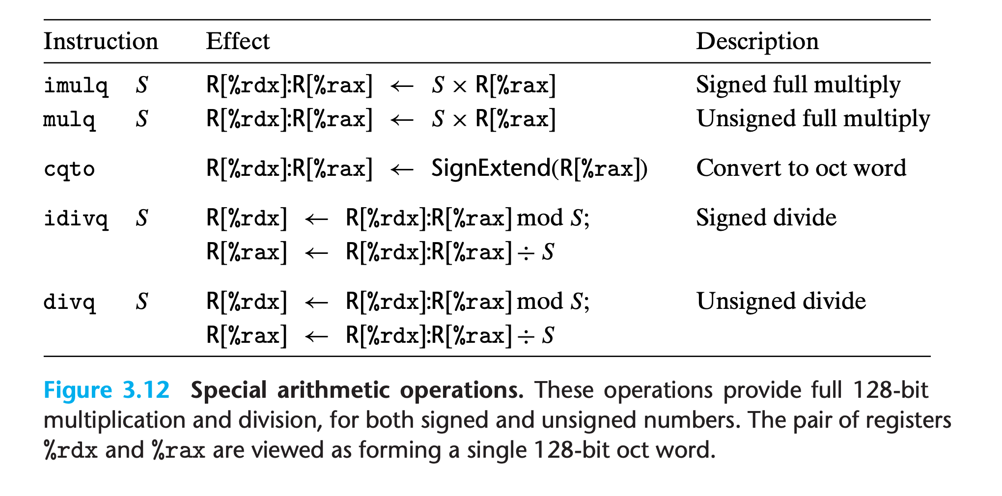
Multiplication instruction class
The imulq instruction has two different forms
imulq S,DIn this form, it serves as a “two operand” multiply instruction, generating a 64-bit product from two 64-bit operands.- Both unsigned multiply and two’s-complement multiply have the same bit-level behavior, so there is only one instruction.
- High-order bits in result are truncated
imulq Sandmulq SCompute the full 128-bit product of two 64-bit values—mulqfor unsigned andimulqfor two’s-complementFor both of these instructions, one argument must be in register
%rax, and the other is given as the instruction source operandThe product is then stored in registers
%rdx(high-order 64 bits) and%rax(low-order 64 bits).Although the name
imulqis used for two distinct multiplication operations, the assembler can tell which one is intended by counting the number of operands.Example
1
2
3
4
5
typedef unsigned __int128 uint128_t;
void store_uprod(uint128_t *dest, uint64_t x, uint64_t y) {
*dest=x* (uint128_t) y;
}1
2
3
4
5
6
7
8#void store_uprod(uint128_t *dest, uint64_t x, uint64_t y)
#dest in %rdi, x in %rsi, y in %rdx
store_uprod:
movq %rsi, %rax #Copy x to multiplicand
mulq %rdx #Multiply by y
movq %rax, (%rdi) #Store lower 8 bytes at dest
movq %rdx, 8(%rdi) #Store upper 8 bytes at dest+8
retDivision instruction class
division and modulus operations are provided by the singleoperand divide instructions similar to the single-operand multiply instructions.
The signed division instruction
idivltakes as its dividend the 128-bit quantity in registers%rdx(high-order 64 bits) and%rax(low-order 64 bits). The divisor is given as the instruction operand.The instruction stores the quotient in register
%raxand the remainder in register%rdx.Usually, the dividend is given as a 64-bit value. This value should be stored in register
%rax. The bits of%rdxshould then be set to either all zeros (unsigned arithmetic) or the sign bit of %rax (signed arithmetic).The latter operation can be performed using the instruction
cqto. This instruction takes no operands—it implicitly reads the sign bit from%raxand copies it across all of%rdx.Example
1
2
3
4
5
6void remdiv(long x, long y,long *qp, long *rp) {
long q = x/y;
long r = x%y;
*qp = q;
*rp = r;
}1
2
3
4
5
6
7
8
9
10# void remdiv(long x, long y, long *qp, long *rp)
# x in %rdi, y in %rsi, qp in %rdx, rp in %rcx
remdiv:
movq %rdx, %r8 # Copy qp, %rdx is required for the division operation
movq %rdi, %rax # Move x to lower 8 bytes of dividend
cqto # Sign-extend to upper 8 bytes of dividend
idivq %rsi # Divide by y
movq %rax, (%r8) # Store quotient at qp
movq %rdx, (%rcx) # Store remainder at rp
retidivqfor signed,divqfor unsigned, the processes are the same.
Practice Problem 3.12
Consider the following function for computing the quotient and remainder of two unsigned 64-bit numbers:
2
3
4
5
6
7
unsigned long *qp, unsigned long *rp) {
unsigned long q = x/y;
unsigned long r = x%y;
*qp = q;
*rp = r;
}Modify the assembly code shown for signed division to implement this function
My solution : :white_check_mark:
1 | # void uremdiv(unsigned long x, unsigned long y, unsigned long *qp, unsigned long *rp) |
Verification:
1 | $ gcc -O2 -S uremdiv.c && ./wash.py uremdiv.s && cat uremdiv.s |
1 | uremdiv: |
Solution on the book :
(compiled with -O1)
1 | #void uremdiv(unsigned long x, unsigned long y, unsigned long *qp, unsigned long *rp) |
Tips
- When converting a function to assembly code,
%rdialways gets the first argument,%rsigets the second one.