4.4 General Principles of Pipelining
Such systems are familiar to anyone who has been through the serving line at a cafeteria or run a car through an automated car wash.
- the task to be performed is divided into a series of discrete stages
- Rather than having one customer run through the entire sequence from beginning to end before the next can begin, we allow multiple customers to proceed through the system at once
- A key feature of pipelining is that it increases the throughput of the system(i.e., the number of customers served per unit time)
- It may also slightly increase the latency (i.e., the time required to service an individual customer)
4.4.1 Computational Pipelines
Some system evaluation property
In contemporary logic design, we measure circuit delays in units of picoseconds (abbreviated “ps”), or $10^{−12}$ seconds
We express throughput in units of giga-instructions per second (abbreviated GIPS), or billions of instructions per second
$$
throughtput = \text{number of output item per second}
$$The total time required to perform a single instruction from beginning to end is known as the latency
Unpiplined system
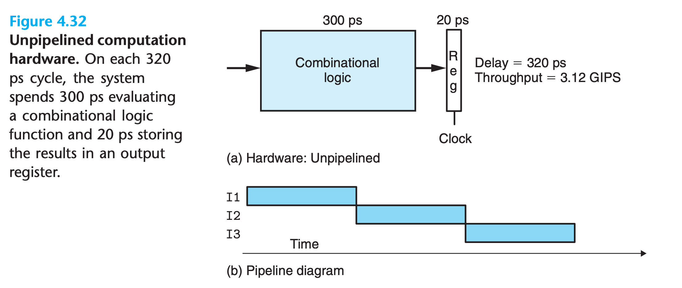
we assume the combinational logic requires 300 ps, while the loading of the register requires 20 ps
In pipline digram:
- A series of instructions (here named I1, I2, and I3) are written from top to bottom.
- time flows from left to right
- The solid rectangles indicate the times during which these instructions are executed
In this implementation, we must complete one instruction before beginning the next. Hence, the boxes do not overlap one another vertically
Piplined system
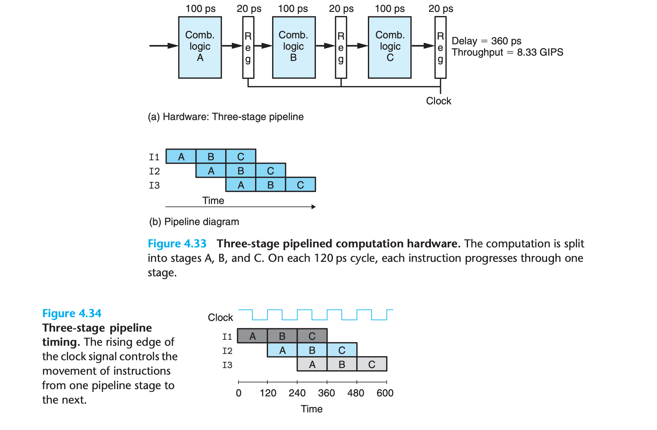
- Suppose we could divide the computation performed by our system into three stages, A, B, and C, where each requires 100 ps
- we could cycle the clocks every 100 + 20 = 120 picoseconds, giving a throughput of around 8.33 GIPS.
- Since processing a single instruction requires 3 clock cycles, the latency of this pipeline is 3 × 120 = 360 ps.
- The increased latency is due to the time overhead of the added pipeline registers.
4.4.2 A Detailed Look at Pipeline Operation
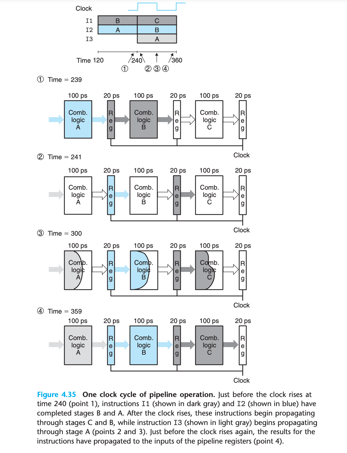
We can see from this detailed view of pipeline operation that slowing down the clock would not change the pipeline behavior.
On the other hand, we could have disastrous effects if the clock were run too fast.
we see that the simple mechanism of having clocked registers between blocks of combinational logic suffices to control the flow of instructions in the pipeline
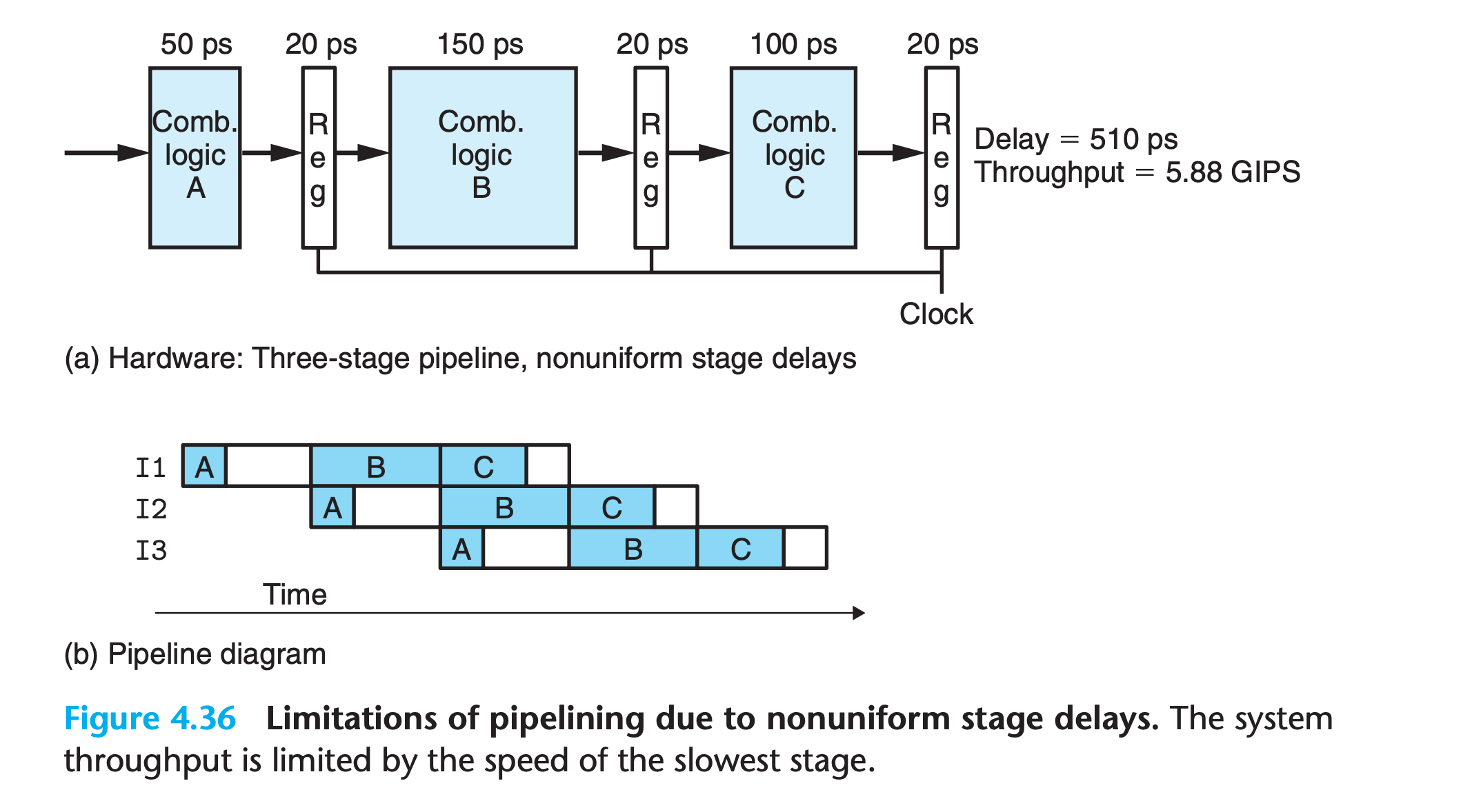
4.4.3 Limitations of Pipelining
Nonuniform Partitioning
the rate at which we can operate the clock is limited by the delay of the slowest stage
- Devising a partitioning of the system computation into a series of stages having uniform delays can be a major challenge for hardware designers.
- some of the hardware units in a processor, such as the ALU and the memories, cannot be subdivided into multiple units with shorter delay.
Practice Problem 4.28
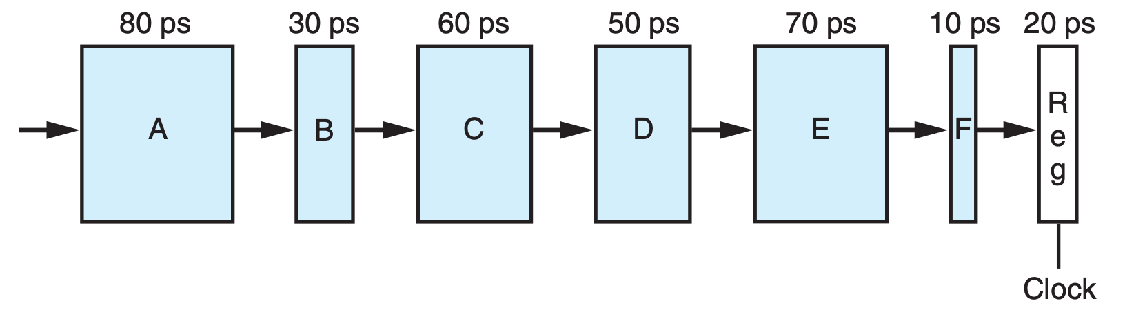
Suppose we analyze the combinational logic of Figure 4.32 and determine that it can be separated into a sequence of six blocks, named A to F, having delays of 80, 30, 60, 50, 70, and 10 ps, respectively, illustrated as follows:
We can create pipelined versions of this design by inserting pipeline registers between pairs of these blocks. Different combinations of pipeline depth (how many stages) and maximum throughput arise, depending on where we insert the pipeline registers. Assume that a pipeline register has a delay of 20 ps.
A. Inserting a single register gives a two-stage pipeline. Where should the register be inserted to maximize throughput? What would be the throughput and latency?
B. Where should two registers be inserted to maximize the throughput of a three-stage pipeline? What would be the throughput and latency?
C. Where should three registers be inserted to maximize the throughput of a 4-stage pipeline? What would be the throughput and latency?
D. What is the minimum number of stages that would yield a design with the maximum achievable throughput? Describe this design, its throughput, and its latency.
My solution : :white_check_mark:
1 | def pipline(maxdelay , stagenum): |
A:
We try to split evenly, so insert between C and D. Then we have :
1 | pipline(190,2) |
B:
Still try to split evenly in order to reduce the maxdelay, so we insert between B,C and D,E
1 | pipline(130,3) |
C:
insert the first one between A and B
insert the second one between C and D
insert the last one between D and E
1 | pipline(110 , 4) |
D:
the maximun throughput is given by split every stage except E and F
1 | pipline(100 , 5) |
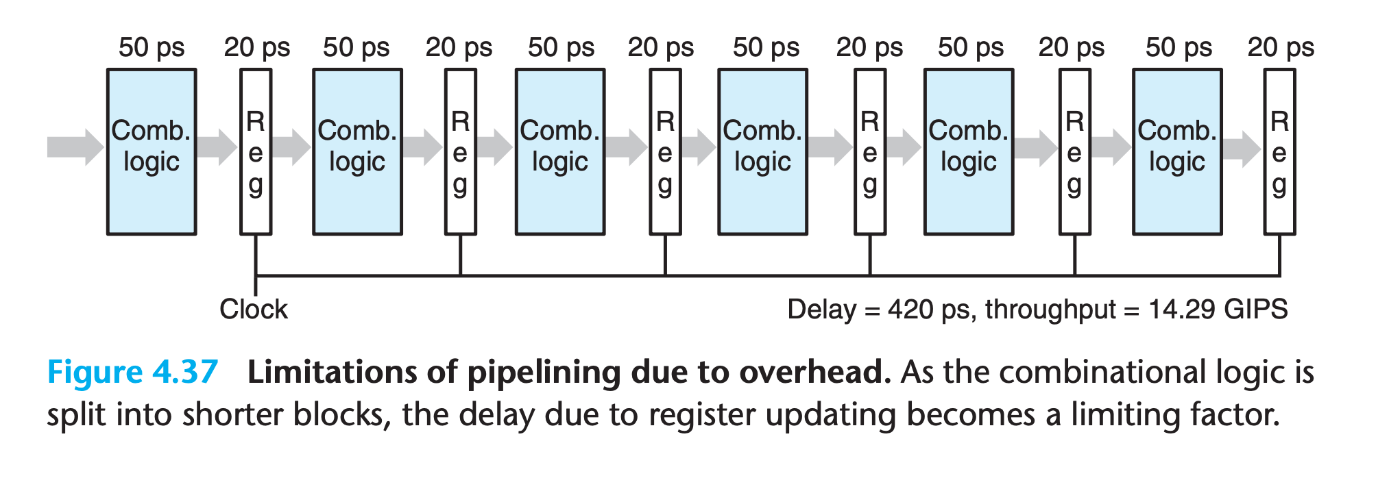
Diminishing Returns of Deep Pipelining
Modern processors employ very deep pipelines (15 or more stages) in an attempt to maximize the processor clock rate.
- The processor architects divide the instruction execution into a large number of very simple steps so that each stage can have a very small delay.
- The circuit designers carefully design the pipeline registers to minimize their delay
- The chip designers must also carefully design the clock distribution network to ensure that the clock changes at the exact same time across the entire chip.
Practice Problem 4.29
Suppose we could take the system of Figure 4.32 and divide it into an arbitrary number of pipeline stages k, each having a delay of 300/k, and with each pipeline register having a delay of 20 ps.
A. What would be the latency and the throughput of the system, as functions of k?
B. What would be the ultimate limit on the throughput?
My solution :
A:
1 | pipline(300/k+20 , k) |
B:
the delay of register
Solution on the book:
B:As we let k go to infinity, the throughput becomes 1,000/20 = 50 GIPS. Of course, the latency would approach infinity as well.
As we try to subdivide the logic into many stages, the latency of the pipeline registers becomes a limiting factor.
4.4.4 Pipelining a System with Feedback
For a system that executes machine programs such as x86-64 or Y86-64, there are potential dependencies between successive instructions.
data dependency
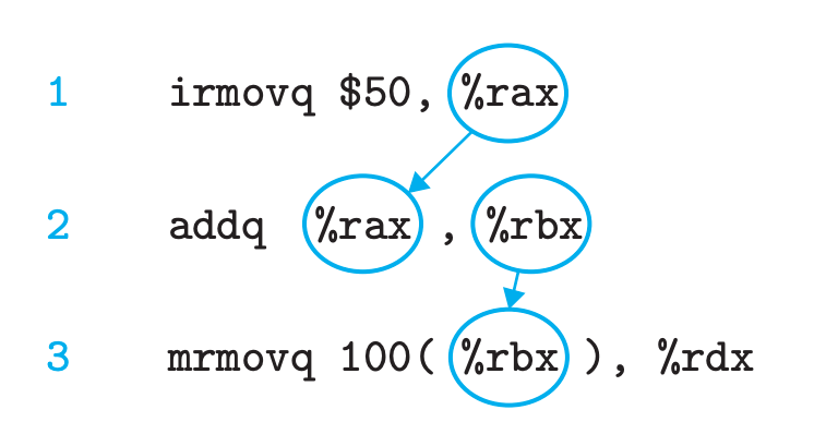
control dependency
1 | loop: |
the outcome of the conditional test determines whether the next instruction to execute will be the irmovq instruction (line 4) or the halt instruction (line 7)
In our design for SEQ, these dependencies were handled by the feedback paths shown on the right-hand side of Figure 4.22.
However, if we attempt to convert this to a three-stage pipeline in the most straightforward manner (Figure 4.38(c)), we change the behavior of the system.(the result of I1 becomes an input to I4)
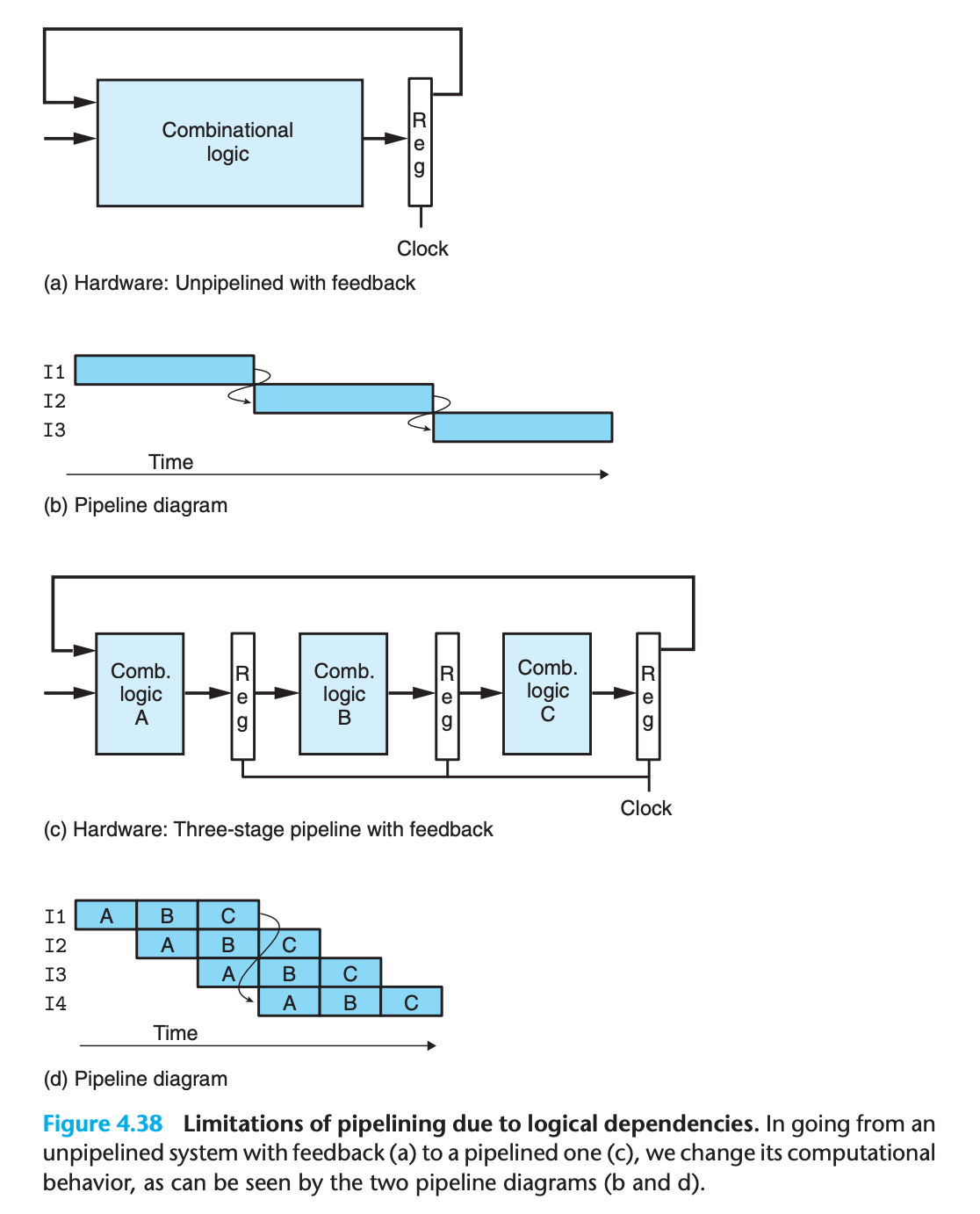
Somehow we must deal with the data and control dependencies between instructions so that the resulting behavior matches the model defined by the ISA.
4.5 Pipelined Y86-64 Implementations
We are finally ready for the major task of this chapter—designing a pipelined Y86- 64 processor
4.5.1 SEQ+: Rearranging the Computation Stages
As a transitional step toward a pipelined design, we must slightly rearrange the order of the five stages in SEQ so that the PC update stage comes at the beginning of the clock cycle, rather than at the end.(We refer to this modified design as SEQ+.)
We can move the PC update stage so that its logic is active at the beginning of the clock cycle by making it compute the PC value for the current instruction
With SEQ+ (Figure 4.39(b)), we create state registers to hold the signals computed during an instruction(previous instruction)
Then, as a new clock cycle begins, the values propagate through the exact same logic to compute the PC for the now-current instruction.
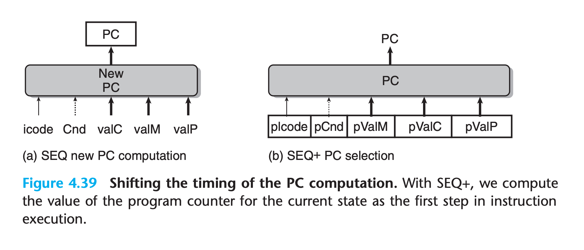
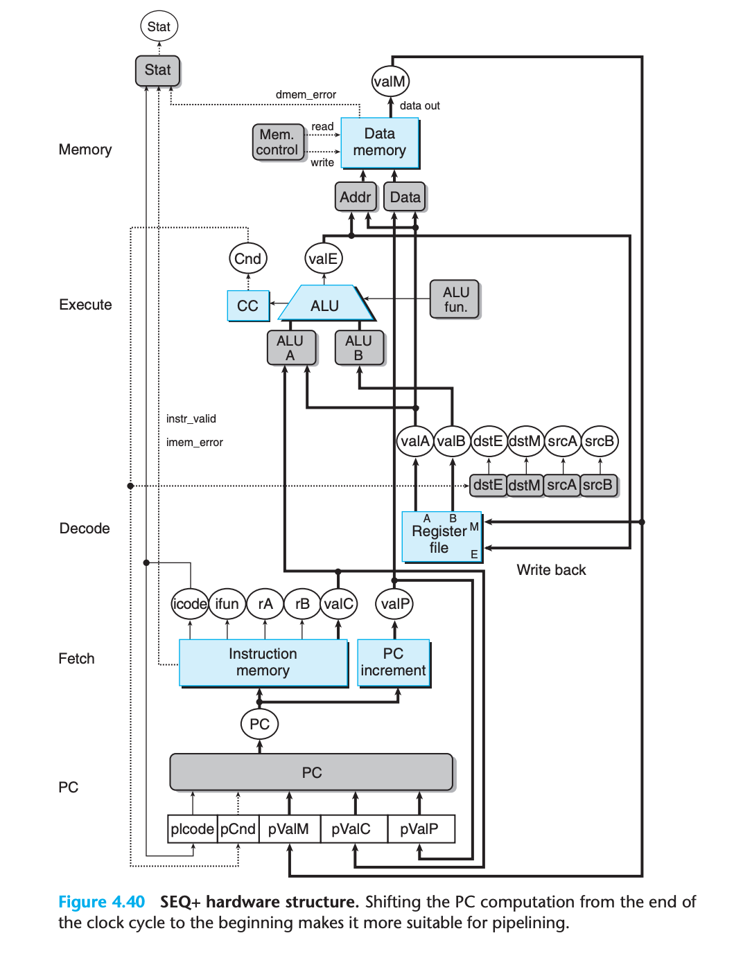
One curious feature of SEQ+ is that there is no hardware register storing the program counter. Instead, the PC is computed dynamically based on some state information stored from the previous instruction.
This is a small illustration of the fact that we can implement a processor in a way that differs from the conceptual model implied by the ISA, as long as the processor correctly executes arbitrary machinelanguage programs.
The shift of state elements from SEQ to SEQ+ is an example of a general transformation known as circuit retiming
Retiming changes the state representation for a system without changing its logical behavior. It is often used to balance the delays between the different stages of a pipelined system.
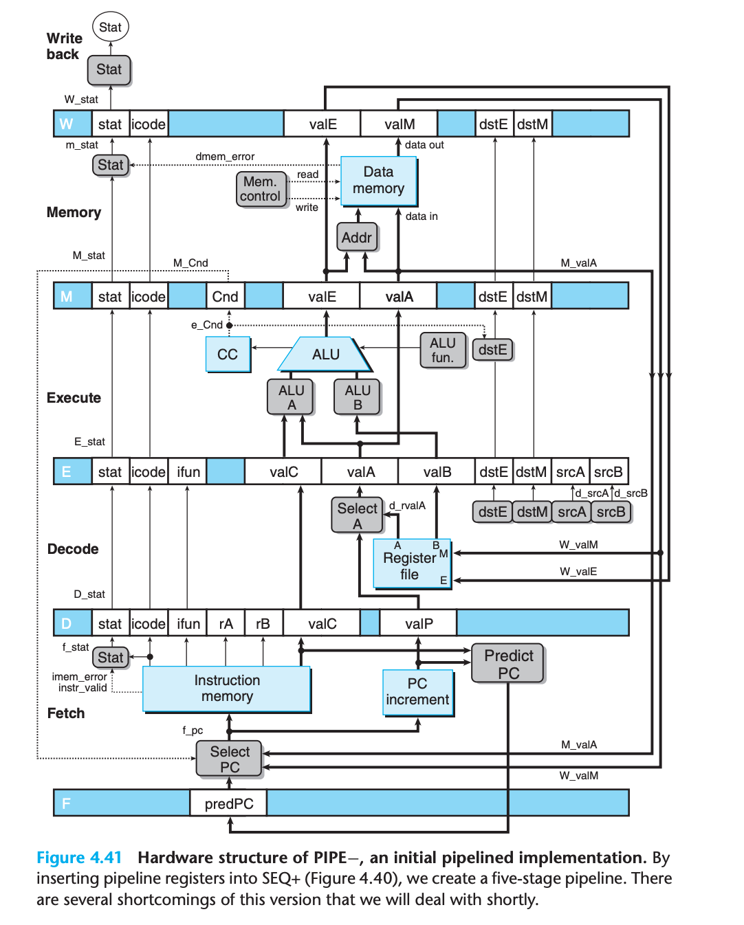
4.5.2 Inserting Pipeline Registers
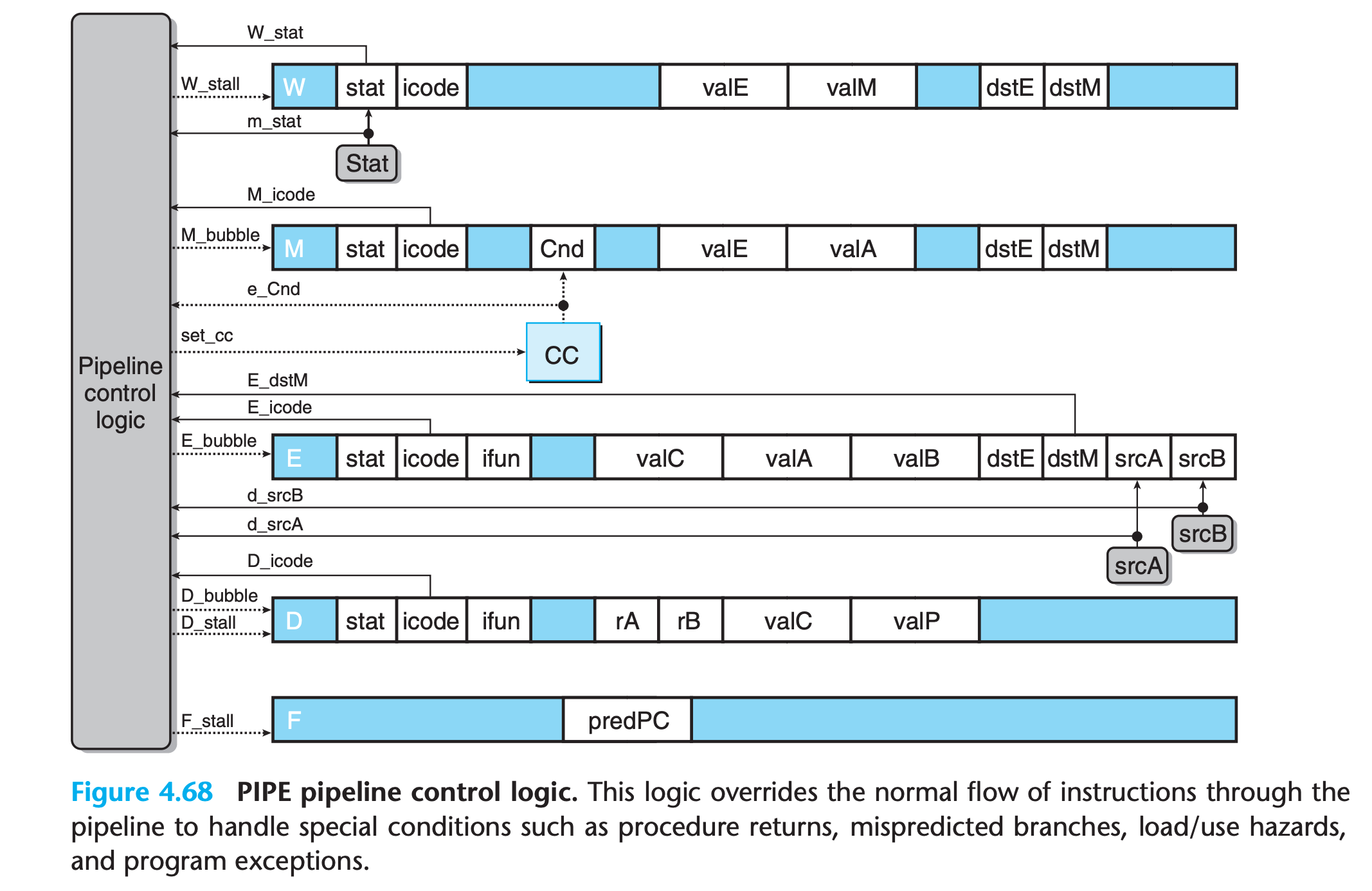
The pipeline registers are shown in this figure as blue boxes, each containing different fields that are shown as white boxes. As indicated by the multiple fields, each pipeline register holds multiple bytes and words.
white boxes represent actual hardware components rather than labels
Fholds a predicted value of the program counterDsits between the fetch and decode stages. It holds information about the most recently fetched instruction for processing by the decode stageEsits between the decode and execute stages. It holds information about the most recently decoded instruction and the values read from the register file for processing by the execute stage.Msits between the execute and memory stages. It holds the results of the most recently executed instruction for processing by the memory stage. It also holds information about branch conditions and branch targets for processing conditional jumps.Wsits between the memory stage and the feedback paths that supply the computed results to the register file for writing and the return address to the PC selection logic when completing a ret instruction.
Then our code execution will be like
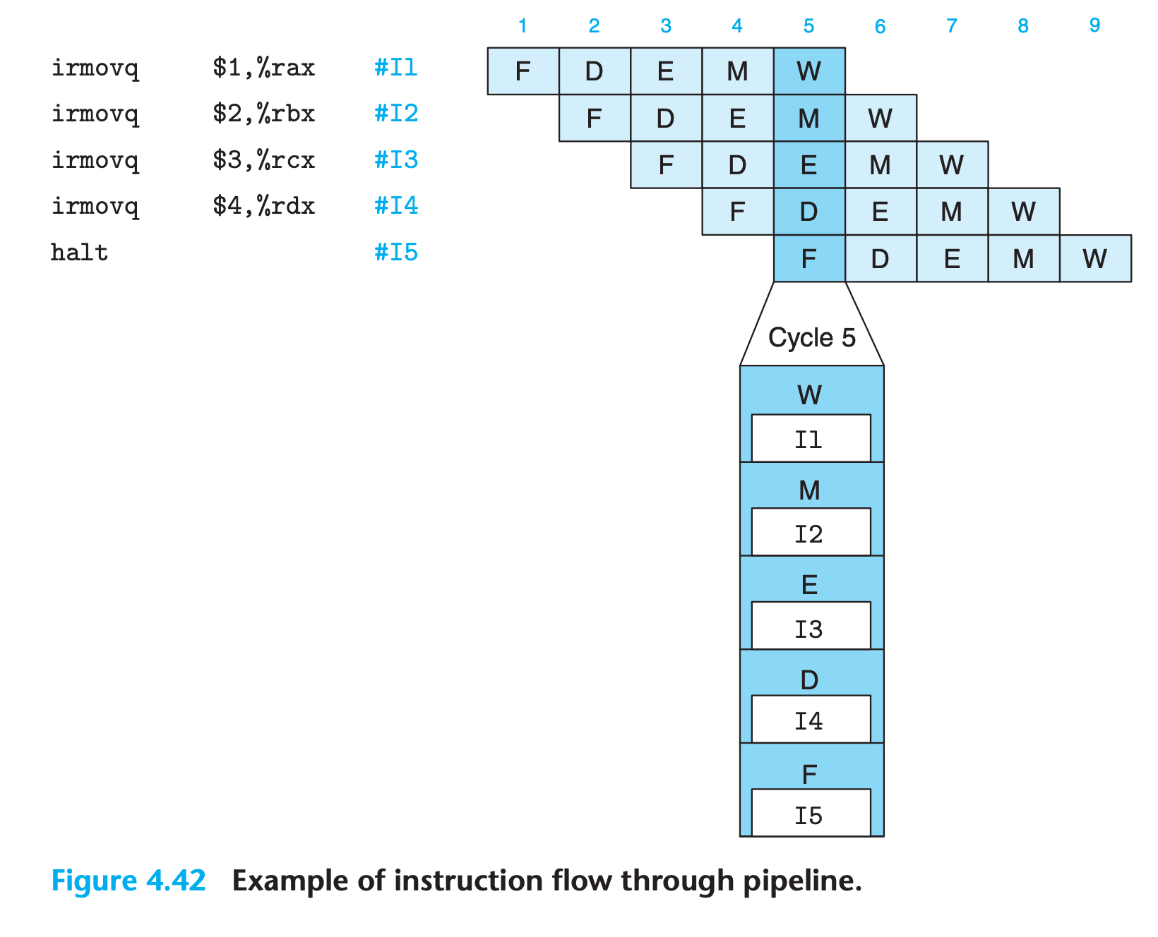
Since normal program flow goes from top to bottom of a listing, we preserve this ordering by having the pipeline flow go from bottom to top.
4.5.3 Rearranging and Relabeling Signals
Aside
What is the difference between signals M_stat and m_stat?
With our naming system, the uppercase prefixes ‘D’, ‘E’, ‘M’, and ‘W’ refer to pipeline registers, and so M_stat refers to the status code field of pipeline register M.
The lowercase prefixes ‘f’, ‘d’, ‘e’, ‘m’, and ‘w’ refer to the pipeline stages, and so m_stat refers to the status signal generated in the memory stage by a control logic block.
Understanding this naming convention is critical to understanding the operation of our pipelined processors.
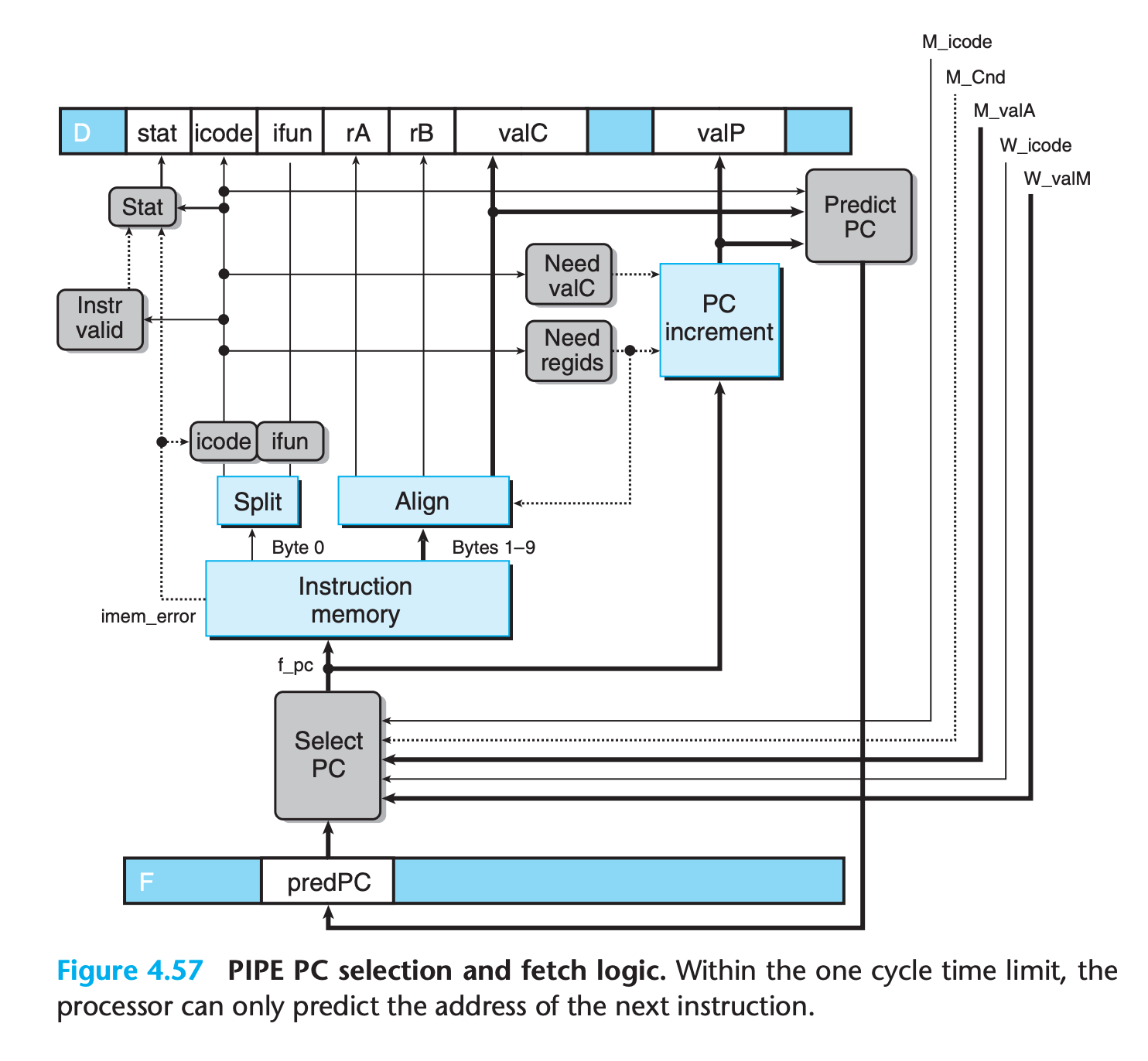
4.5.4 Next PC Prediction
In pipline, we must determine the location of the next instruction right after fetching the current instruction.
Unfortunately, if the instruction is ret or conditional branch, we cannot determine the address of next instruction until execution stage or memory stage
Except these two instructions, the address of the next instruction can be predicated based on information computed during the fetch stage.
We can therefore achieve our goal of issuing a new instruction every clock cycle in most cases by predicting the next value of the PC.
Extensive experiments have been conducted on effective strategies for predicting whether or not branches will be taken(and large amount of hardware to implement them)
In our design, we simply assume all condition is taken for branches.
For ret instruction, we just stop fetch new instruction until the ret is finished.
4.5.5 Pipeline Hazards
Resulted from dependencies, hazards can be classified as either data hazards or control hazards
Data hazard
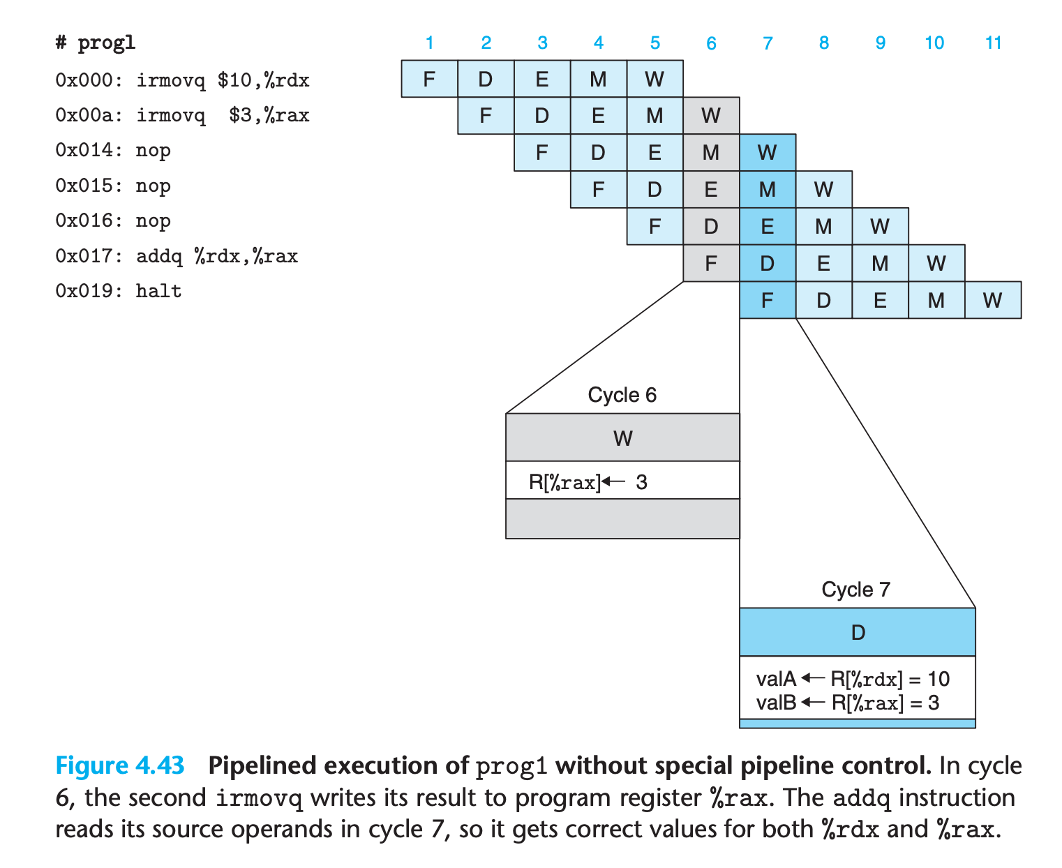
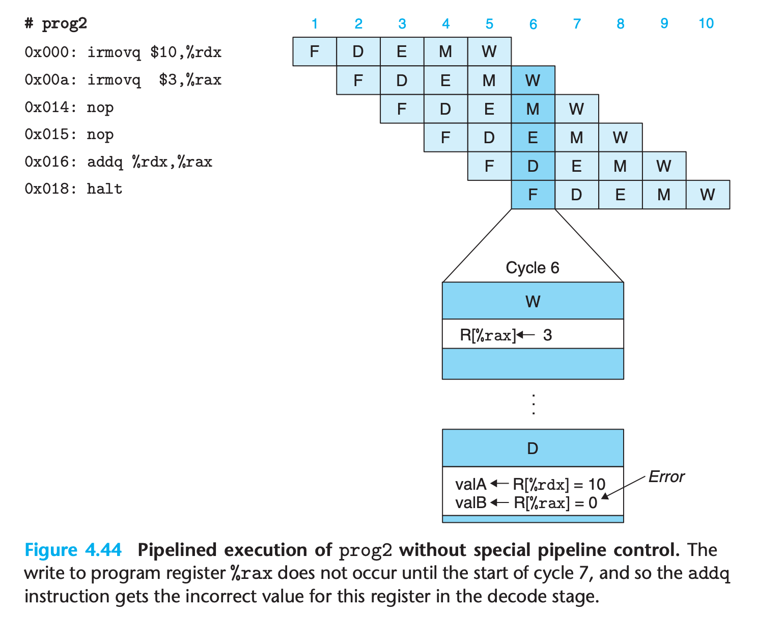
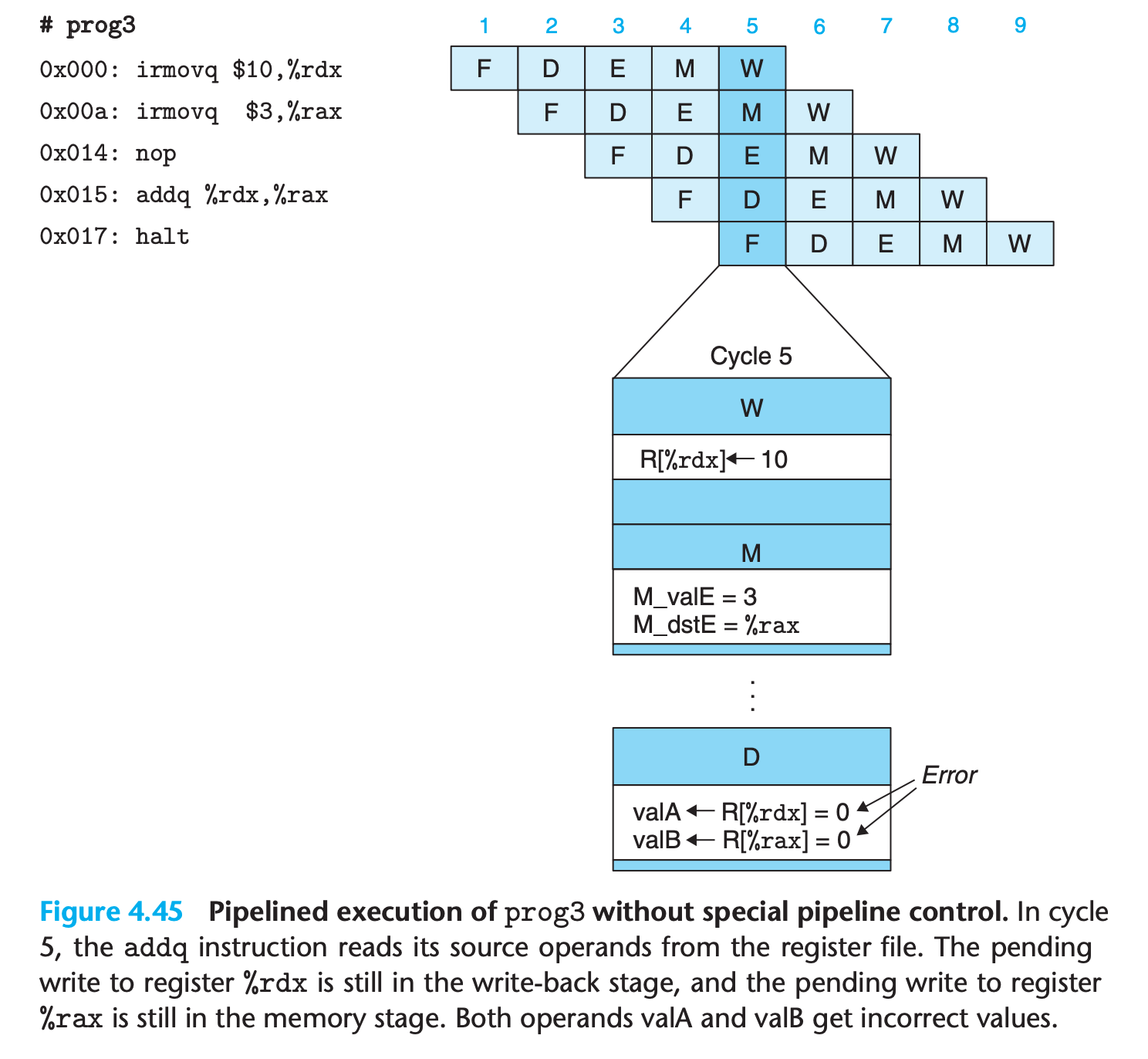
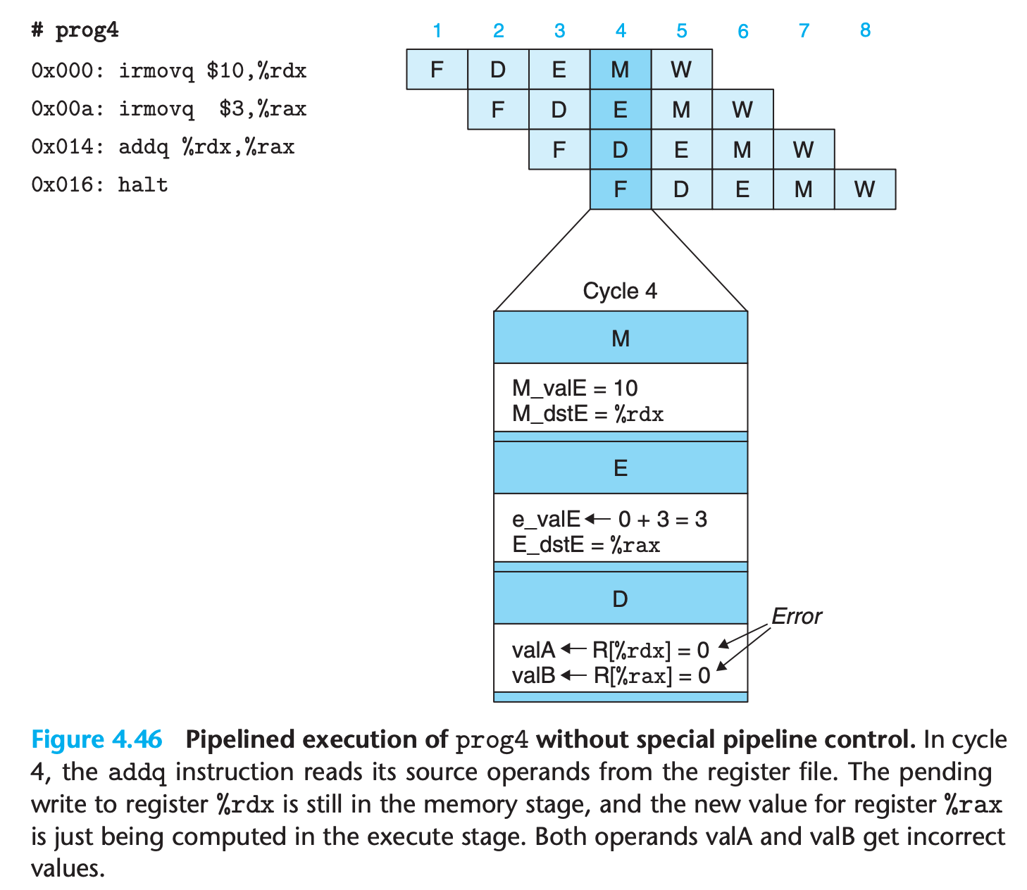
These examples illustrate that a data hazard can arise for an instruction when one of its operands is updated by any of the three preceding instructions. These hazards occur because our pipelined processor reads the operands for an instruction from the register file in the decode stage but does not write the results for the instruction to the register file until three cycles later, after the instruction passes through the write-back stage.
Avoiding Data Hazards by Stalling
One very general technique for avoiding hazards involves stalling, where the processor holds back one or more instructions in the pipeline until the hazard condition no longer holds
- It involves simple enhancements to the pipeline control logic
- it has the same effect like adding
nopinstruction, which has shown above
For example
When the addq instruction is in the decode stage, the pipeline control logic detects that at least one of the instructions in the execute, memory, or write-back stage will update either register %rdx or register %rax. Rather than letting the addq instruction pass through the stage with the incorrect results, it stalls the instruction, holding it back in the decode stage for either one (for prog2) or three (for prog4) extra cycles.
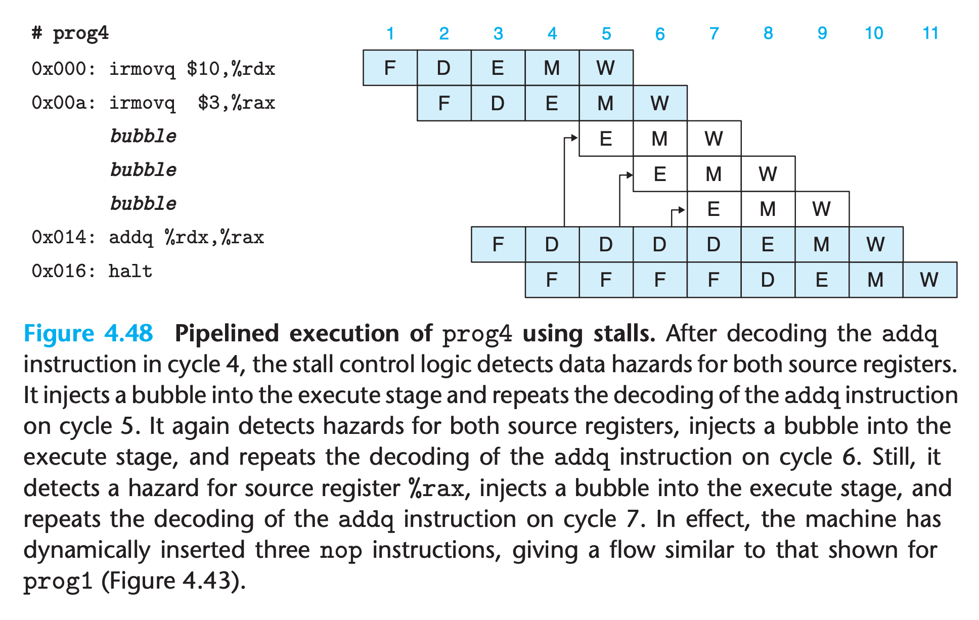
(We also need to keep PC a fixed value when stalling)
This mechanism can be implemented fairly easily, but the resulting performance is not very good
There are numerous cases in which one instruction updates a register and a closely following instruction uses the same register. This will cause the pipeline to stall for up to three cycles, reducing the overall throughput significantly
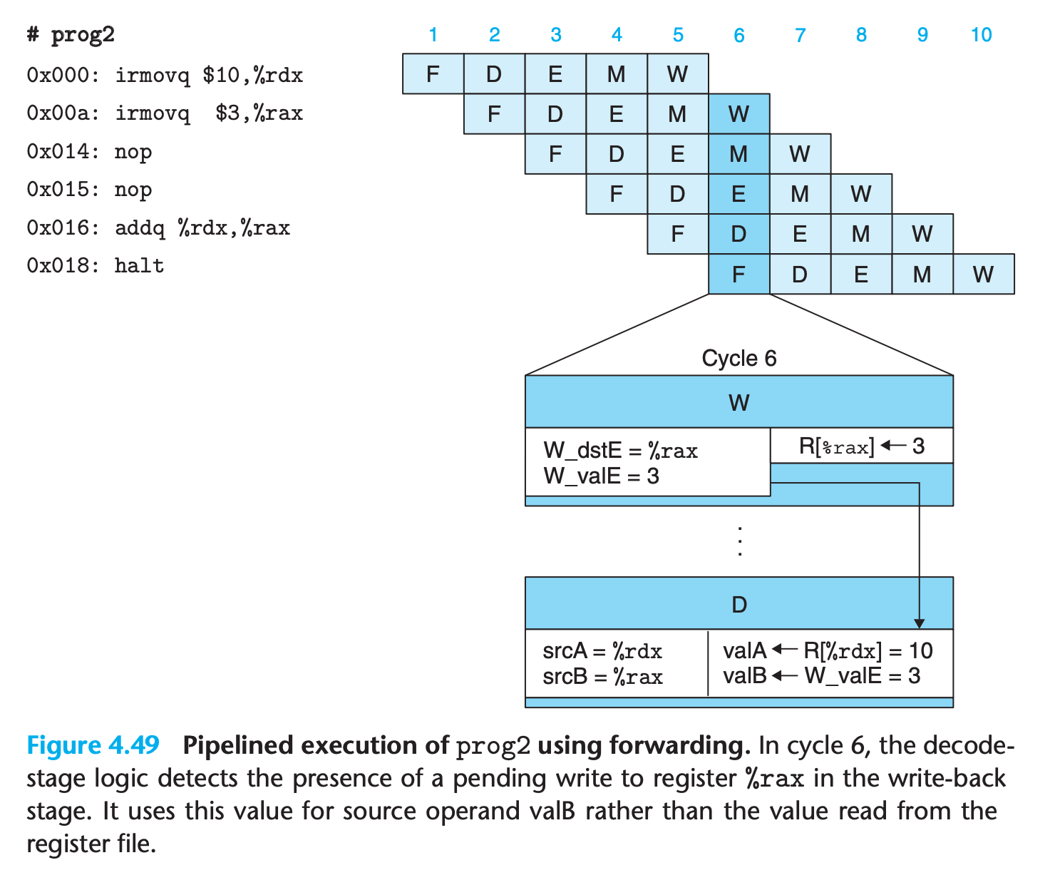
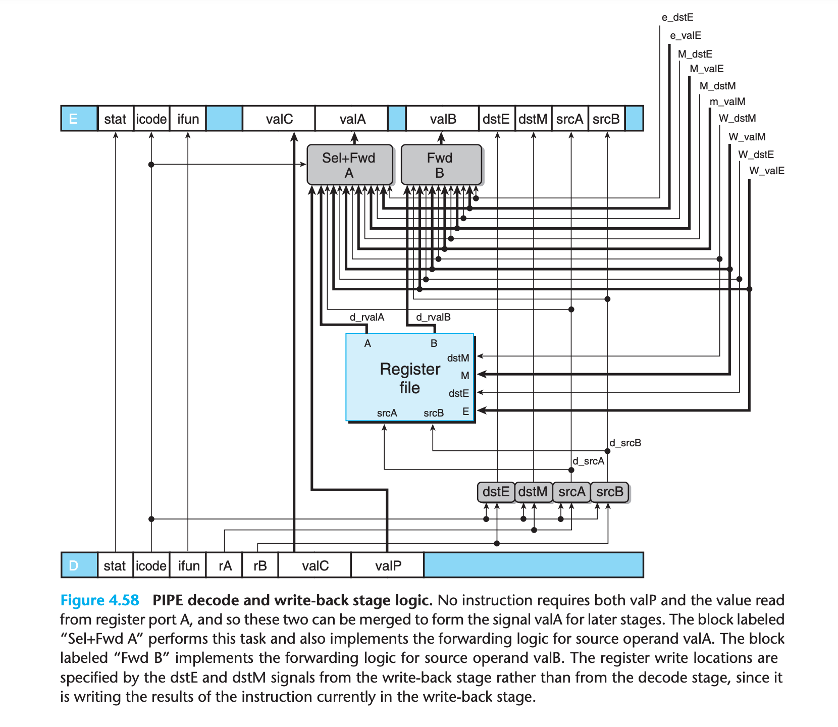
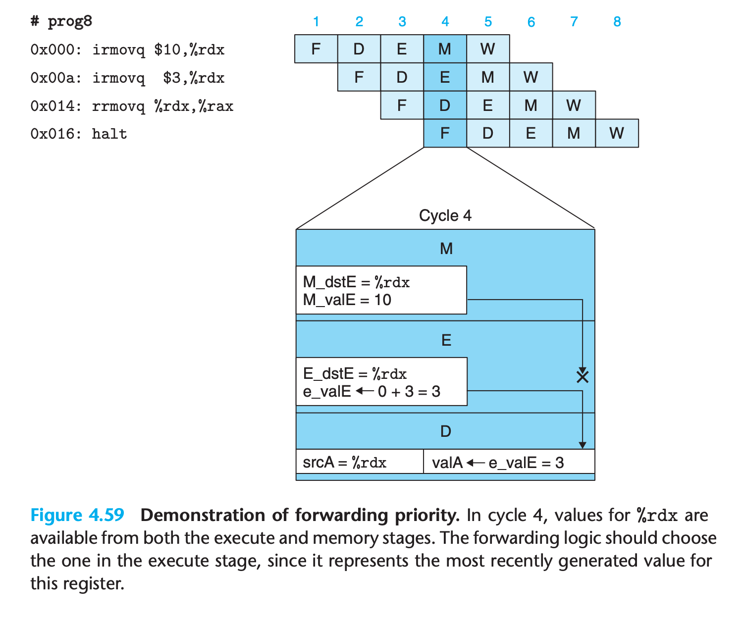
Avoiding Data Hazards by Forwarding
If there are register to be updated, forwarding the pended value in previous stages to register access result
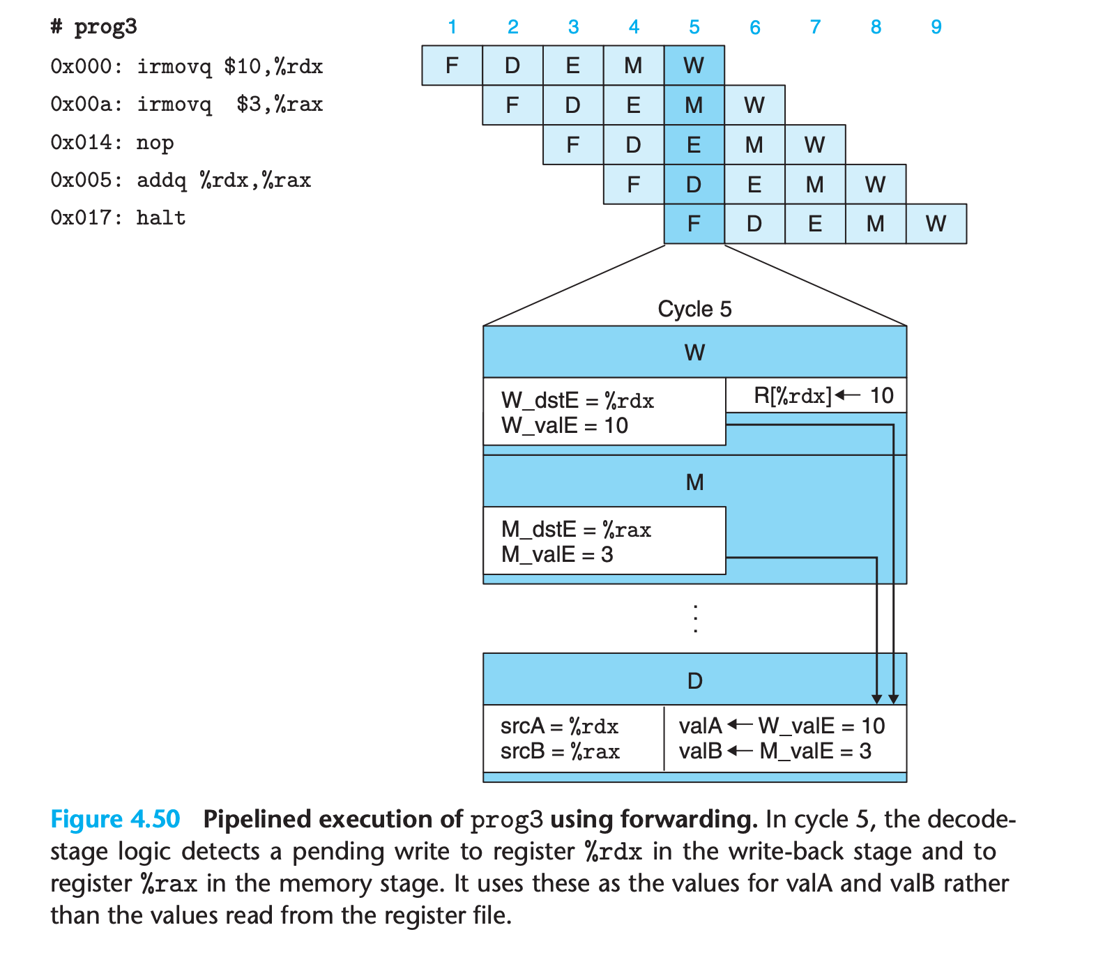
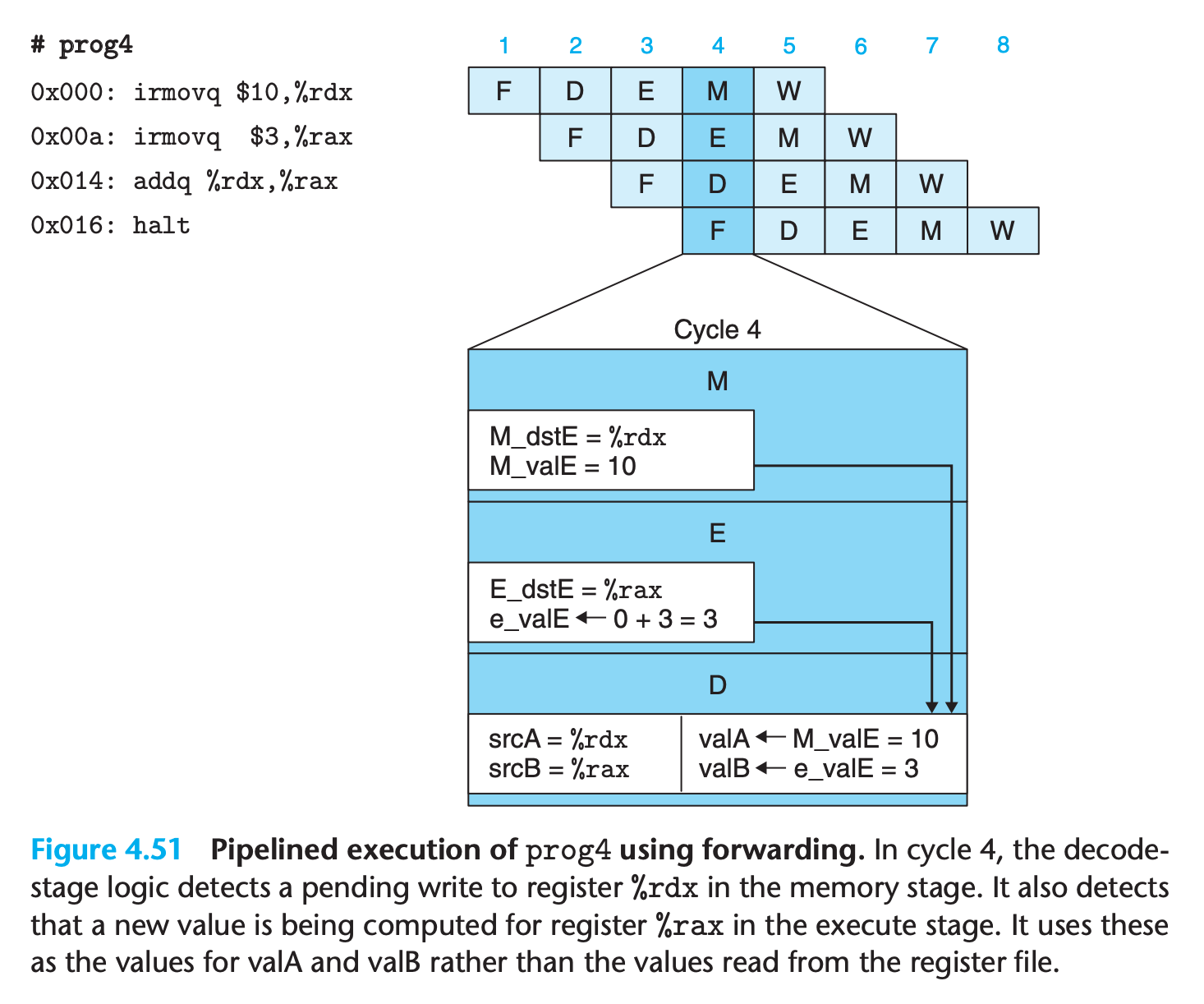
This gives a total of five different forwarding sources (e_valE, m_valM, M_valE, W_valM, and W_valE) and two different forwarding destinations (valA and valB).
- This technique of passing a result value directly from one pipeline stage to an earlier one is commonly known as data forwarding
- Data forwarding requires adding additional data connections and control logic to the basic hardware structure.
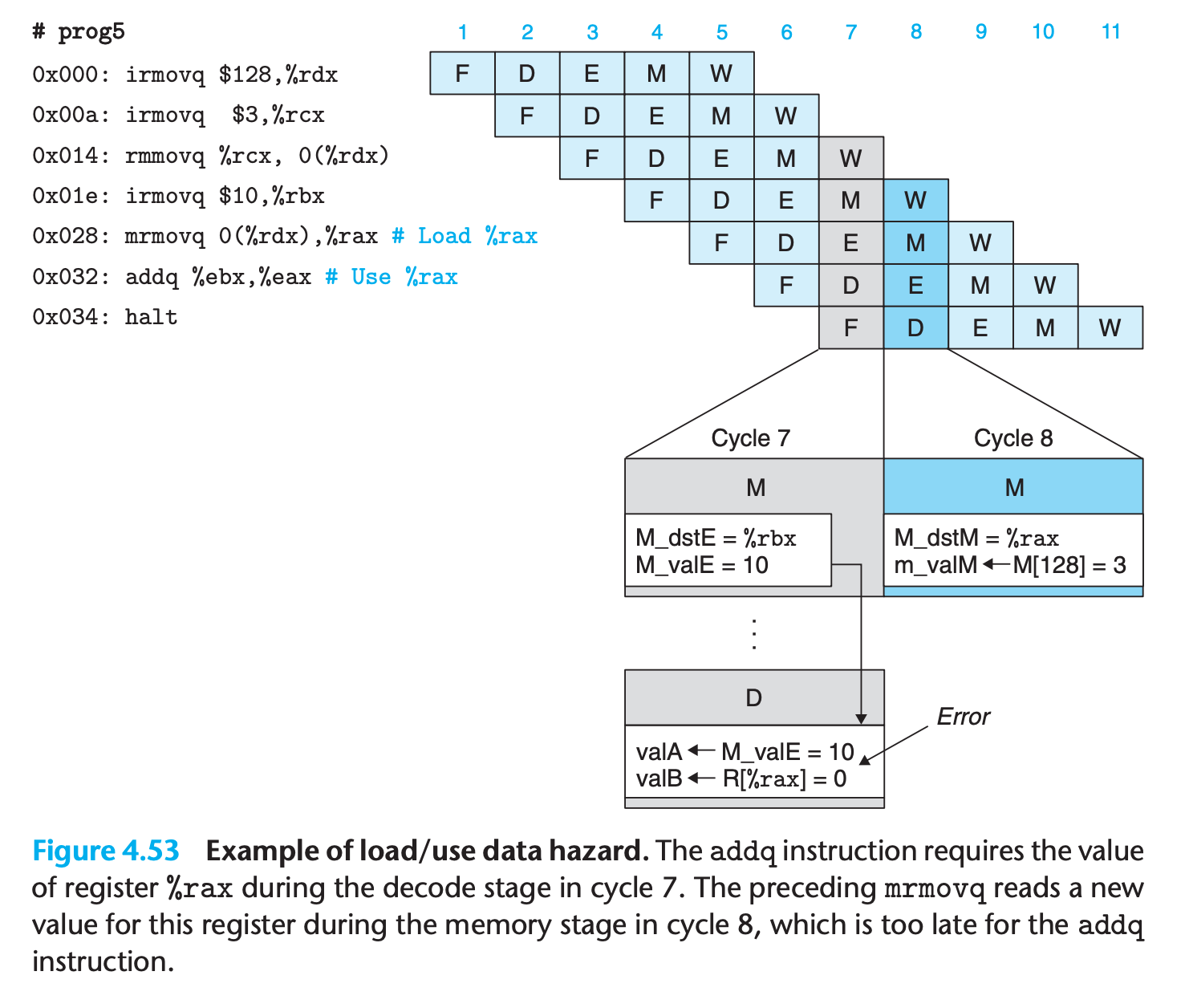
Load/Use Data Hazards
Forwarding cannot handle the situation that the value used to update the register is read from memory, since it must wait for the value to be read.
we can avoid a load/use data hazard with a combination of stalling and forwarding
This requires modifications of the control logic, but it can use existing bypass paths
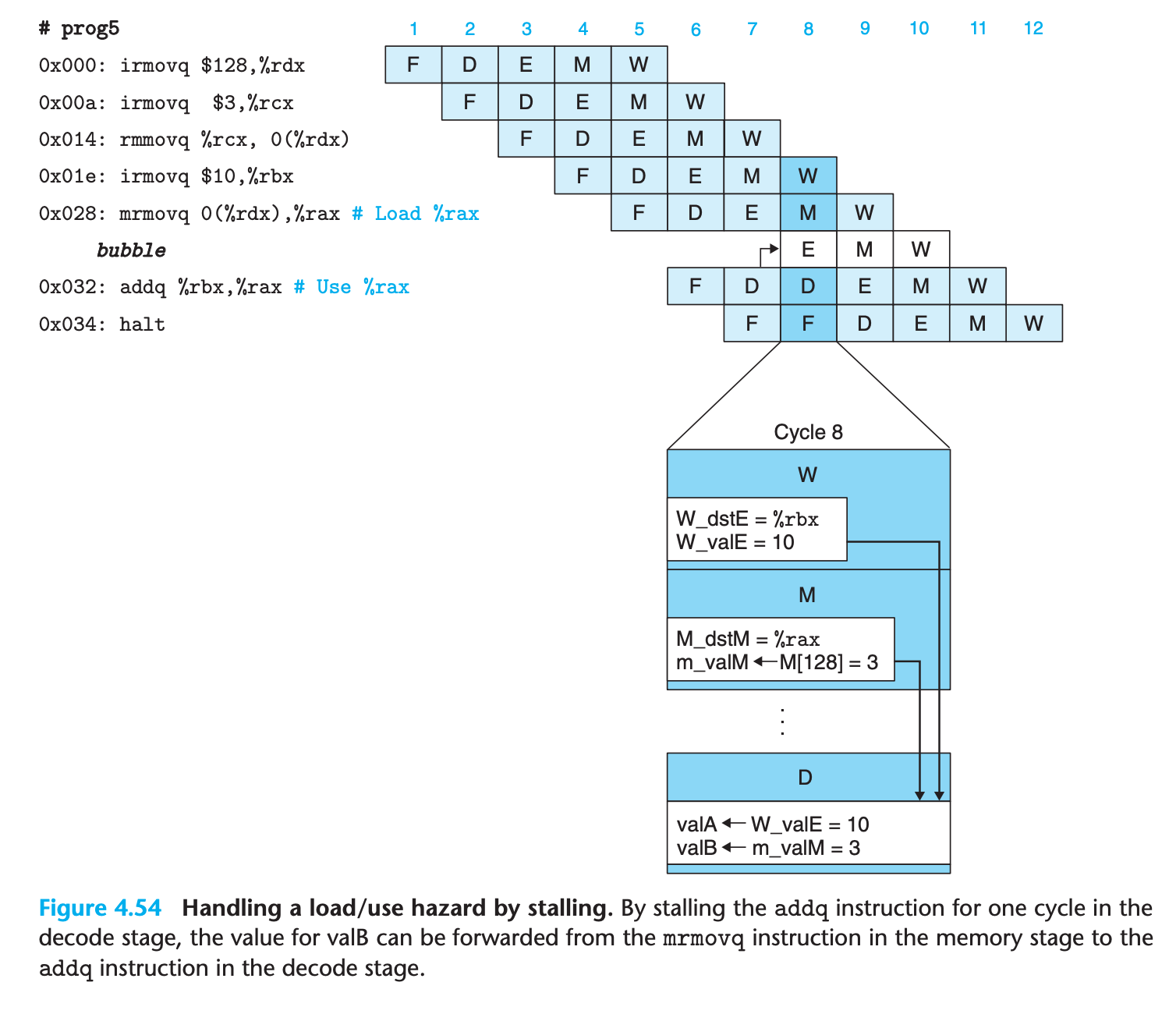
This use of a stall to handle a load/use hazard is called a load interlock.
Load interlocks combined with forwarding suffice to handle all possible forms of data hazards. Since only load interlocks reduce the pipeline throughput, we can nearly achieve our throughput goal of issuing one new instruction on every clock cycle.
Avoiding Control Hazards
Control hazards arise when the processor cannot reliably determine the address of the next instruction based on the current instruction in the fetch stage.
ret hazard
For example when executing the following codes
1 | 0x000: irmovq stack,%rsp # Initialize stack pointer |
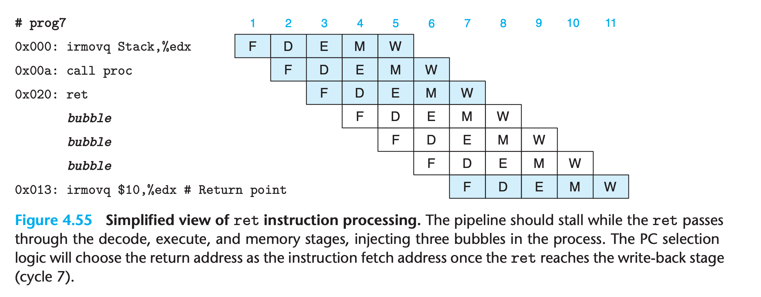
Once the ret instruction reaches the write-back stage, the PC selection logic will set the program counter to the return address, and therefore the fetch stage will fetch the irmovq instruction at the return point
Mispredicate hazard
For example
1 | 0x000: xorq %rax,%rax |
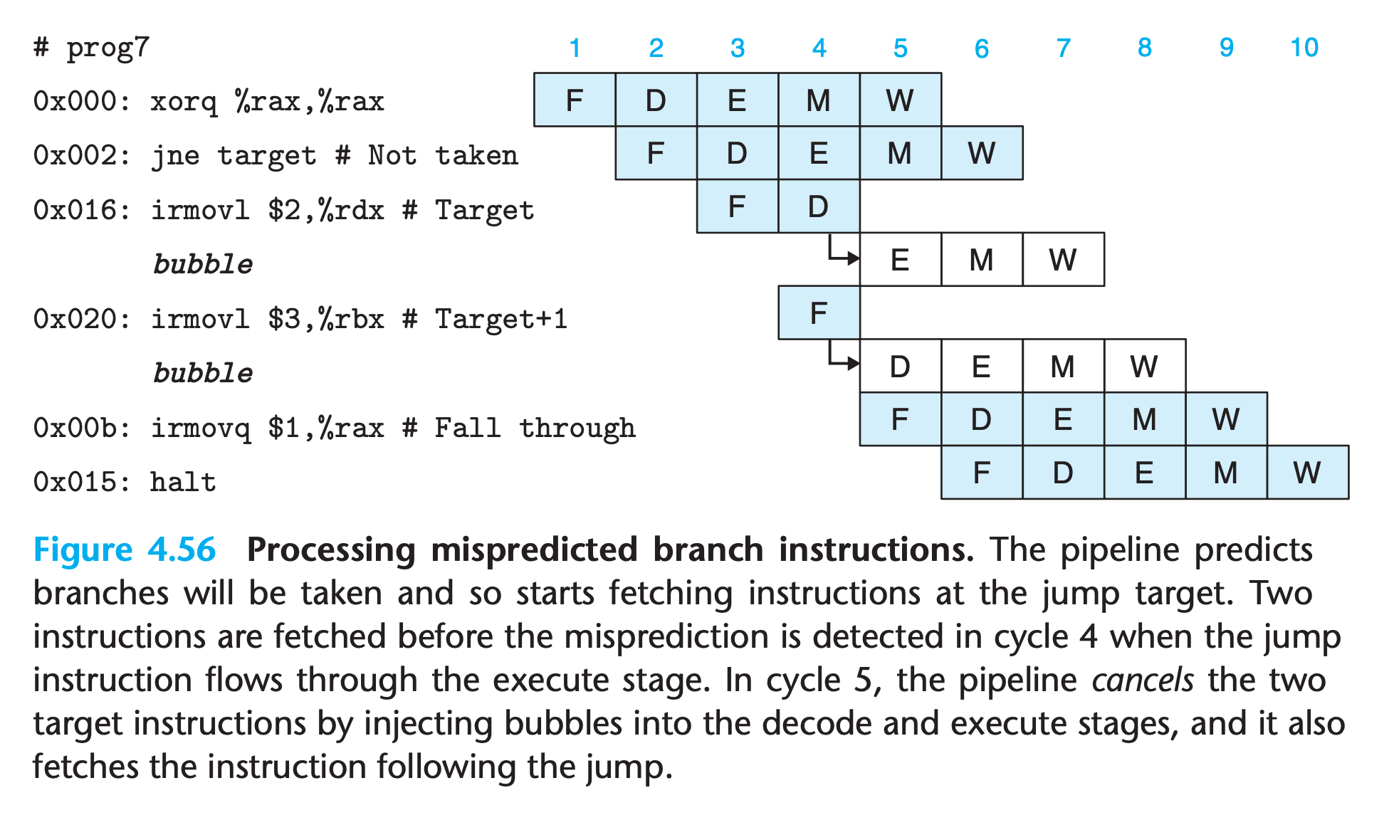
- Since the jump instruction is predicted as being taken, the instruction at the jump target will be fetched in cycle 3
- By the time the branch logic detects that the jump should not be taken during cycle 4, two instructions have been fetched that should not continue being executed
- Fortunately, neither of these instructions has caused a change in the programmer-visible state(Not reach the execution stage)
- the pipeline can simply cancel the two misfetched instructions by injecting bubbles into the decode and execute stages on the following cycle while also fetching the instruction following the jump instruction.
- The two misfetched instructions will then simply disappear from the pipeline and therefore not have any effect on the programmer-visible state.
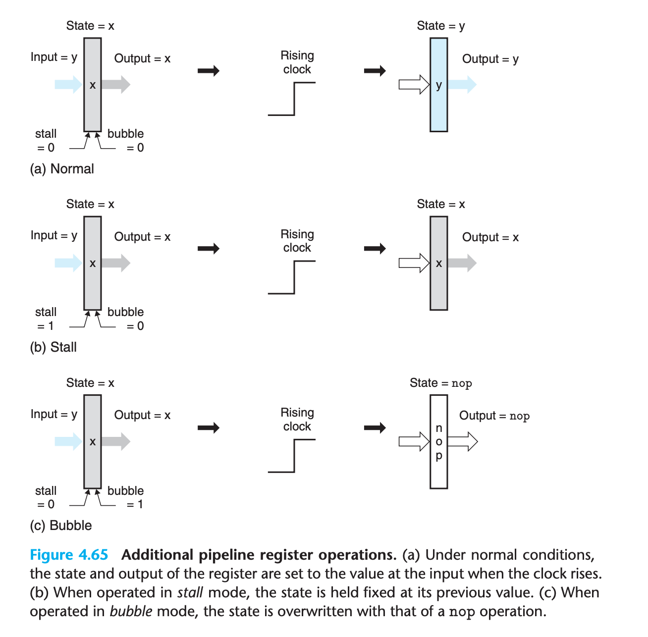
a simple extension to the basic clocked register design will enable us to stall stages and to inject bubbles into pipeline registers as part of the pipeline control logic.
4.5.6 Exception Handling
a variety of activities in a processor can lead to exceptional control flow, where the normal chain of program execution gets broken.
Exceptions can be generated either internally, by the executing program, or externally, by some outside signal.
A more complete processor design would also handle external exceptions, such as when the processor receives a signal that the network interface has received a new packet or the user has clicked a mouse button
(Handling exceptions correctly is a challenging aspect of any microprocessor design. They can occur at unpredictable times, and they require creating a clean break in the flow of instructions through the processor pipeline)
It should appear that all instructions up to the excepting instruction have completed, but none of the following instructions should have any effect on the programmer-visible state.
In a more complete design, the processor would continue by invoking an exception handler, a procedure that is part of the operating system
In a pipelined system, exception handling involves several subtleties.
It is possible to have exceptions triggered by multiple instructions simultaneously
For example, in one clock cycle, fetch stage fetchs a
haltand memory stage has ainvalid memory addressSo which exception should we report?
The basic rule is to put priority on the exception triggered by the instruction that is furthest along the pipeline
(In terms of the machine-language program, the instruction in the memory stage should appear to execute before one in the fetch stage, and therefore only this exception should be reported to the operating system.)
When an instruction first fetched and begins execution, causes an exception, and later is canceled due to a mispredicted branch.
1
2
3
4
5
60x000: 6300 | xorq %rax,%rax
0x002: 741600000000000000 | jne target # Not taken
0x00b: 30f00100000000000000 | irmovq $1, %rax # Fall through
0x015: 00 | halt
0x016: | target:
0x016: ff | .byte 0xFF # Invalid instruction code The pipeline control logic will cancel the invalid instruction, but we want to avoid raising an exception.
It is possible for an instruction following one causing an exception to alter some part of the state before the excepting was detected
1
2
3
4irmovq $1,%rax
xorq %rsp,%rsp # Set stack pointer to 0 and CC to 100
pushq %rax # Attempt to write to 0xfffffffffffffff8, detected in memory stage
addq %rax,%rax # (Should not be executed) Would set CC to 000we can both correctly choose among the different exceptions and avoid raising exceptions for instructions that are fetched due to mispredicted branches by merging the exception-handling logic into the pipeline structure. That is the motivation for us to include a status code statin each of our pipeline registers
If an instruction generates an exception at some stage in its processing, the status field is set to indicate the nature of the exception. The exception status propagates through the pipeline with the rest of the information for that instruction, until it reaches the write-back stage. At this point, the pipeline control logic detects the occurrence of the exception and stops execution.
The simple rule of carrying the exception status together with all other information about an instruction through the pipeline provides a simple and reliable mechanism for handling exceptions.
The pipline like a queue, FIFO, so it follows the order indicated by assembly language
When reach write back stage and an exception was detected, the processor will disable any updating of the programmer-visible state (the condition code register and the memory) by later instructions in the pipeline(make those devices unwritable)
If some instruction is fetched but later canceled, any exception status information about the instruction gets canceled as well.
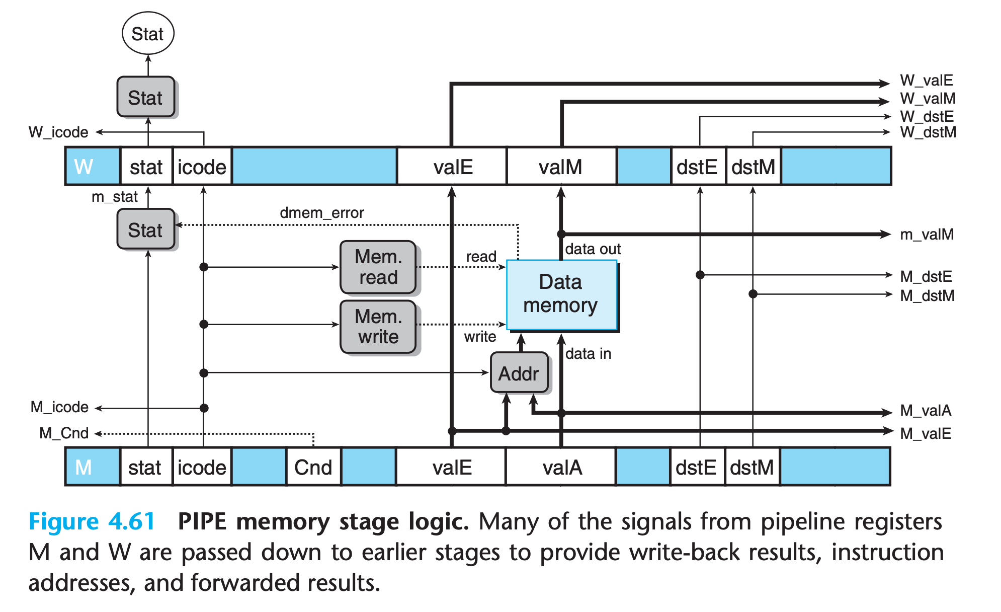
4.5.7 PIPE Stage Implementations
Many of the logic blocks are identical to their counterparts in SEQ and SEQ+, except that we must choose proper versions of the different signals from the pipeline registers (written with the pipeline register name, written in uppercase, as a prefix) or from the stage computations (written with the first character of the stage name, written in lowercase, as a prefix).
the complete HCL code for PIPE is given in Web Aside arch:hcl on page 508.
PC Selection and Fetch Stage
The PC selection logic chooses between three program counter sources
Decode and Write-Back Stages
we want the writes to occur to the destination registers specified by the instruction in the write-back stage
1 | word d_valA = [ |
The priority given to the five forwarding sources in the above HCL code is very important.
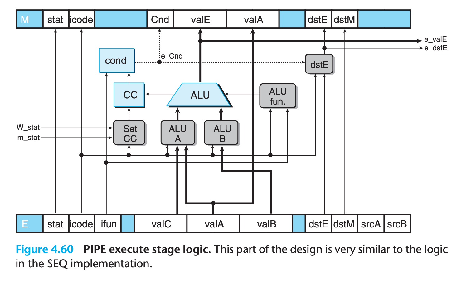
Execute Stage
The hardware units and the logic blocks are identical to those in SEQ, with an appropriate renaming of signals.
One difference is that the logic labeled “Set CC,” which determines whether or not to update the condition codes, has signals m_stat and W_stat as inputs.
These signals are used to detect cases where an instruction causing an exception is passing through later pipeline stages, and therefore any updating of the condition codes should be suppressed
Memory Stage
4.5.8 Pipeline Control Logic
We are now ready to complete our design for PIPE by creating the pipeline control logic.
Only 4 problems left:
- Load/use hazards.
- Processing ret.
- Mispredicted branches.
- Exceptions
Desired Handling of Special Control Cases
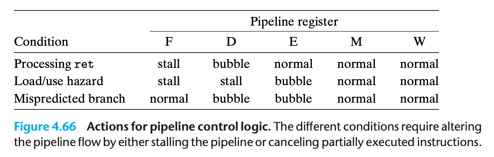
In summary, implementing this pipeline flow requires detecting the hazard condition, keeping pipeline registers F and D fixed, and injecting a bubble into the execute stage.
Detecting Special Control Conditions
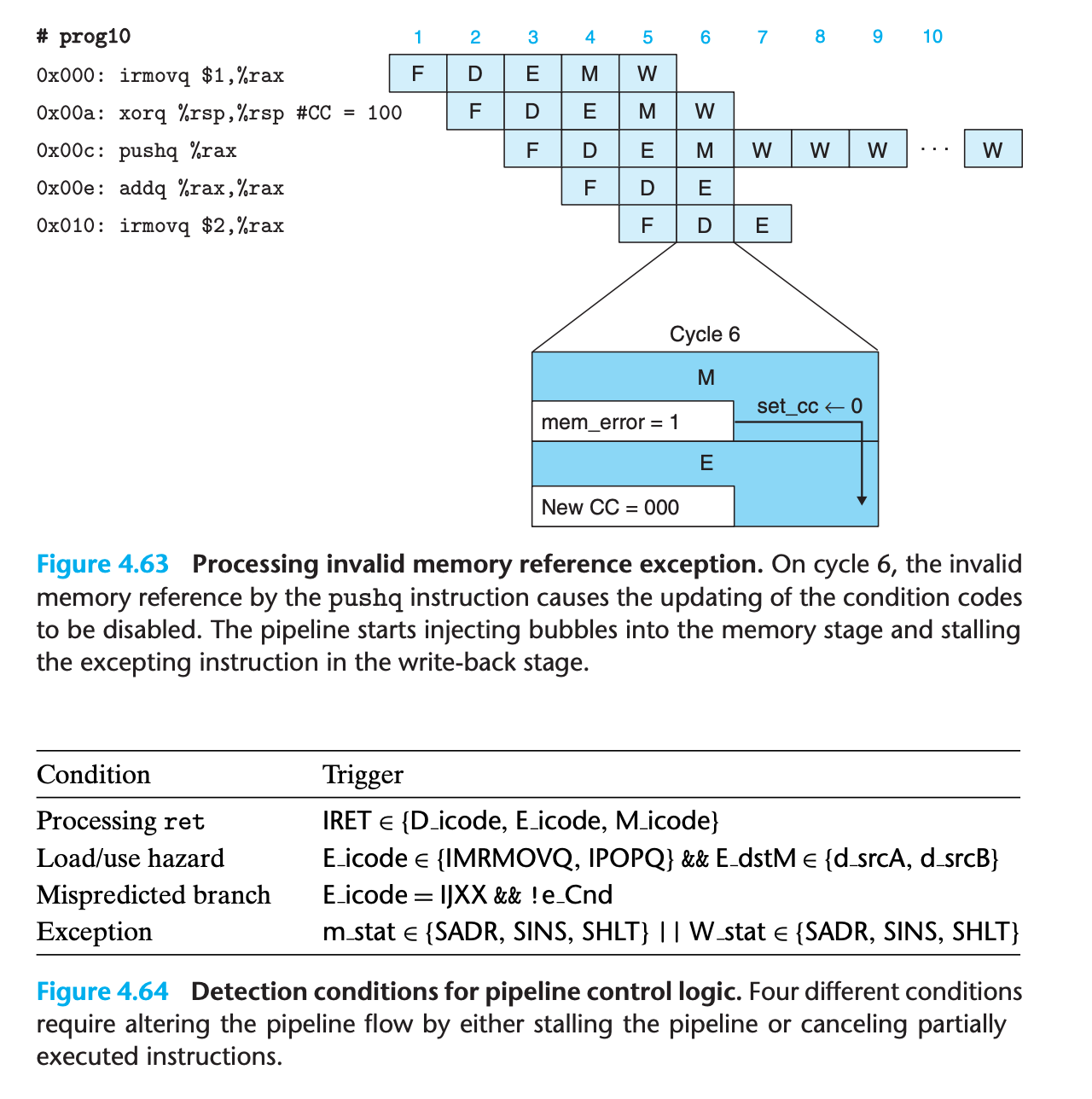
Pipeline Control Mechanisms
These mechanisms involve small extensions to the basic clocked register described
Combinations of Control Conditions
A common bug in designing a system is to fail to handle instances where multiple special conditions arise simultaneously
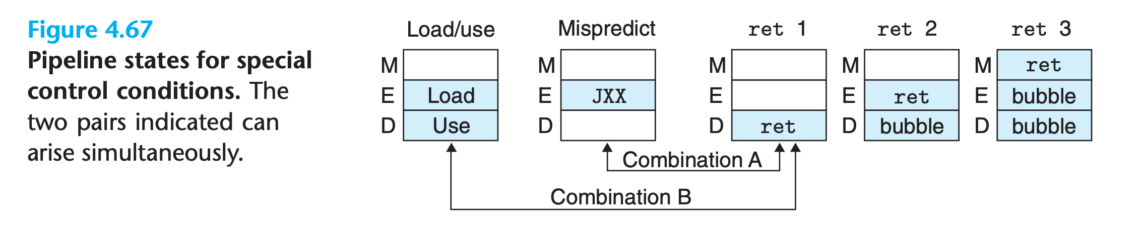
We can see by these diagrams that most of the control conditions are mutually exclusive.Only the two combinations indicated by arrows can arise simultaneously.
The pipeline control logic should detect that the branch was mispredicted and therefore cancel the ret instruction
Control Logic Implementation
4.5.9 Performance Analysis
We can measure the inefficiency by determining how often a bubble gets injected into the pipeline, since these cause unused pipeline cycles.
We can quantify the effect these penalties have on the overall performance by computing an estimate of the average number of clock cycles PIPE would require per instruction it executes, a measure known as the CPI
How do we know our implementation of ISA is correct? We cannot test all combinations of instructions since they are nearly infinite.
Newer methods of formal verification, however, hold the promise that we can have tools that rigorously consider all possible behaviors of a system and determine whether or not there are any design errors
4.5.10 Unfinished Business
Still, PIPE lacks several key features that would be required in an actual microprocessor design.
Multicycle Instructions
In a more complete instruction set, we would also need to implement instructions requiring more complex operations such as integer multiplication and division and floating-point operations
Interfacing with the Memory System
- We ignored the possible hazards caused by self-modifying code where one instruction writes to the region of memory from which later instructions are fetched.
- we reference memory locations according to their virtual addresses, and these require a translation into physical addresses before the actual read or write operation can be performed.(So more than one clock cycle was needed)
However, using a combination of TLBs and caches, it is indeed possible to read instructions and read or write data in a single clock cycle most of the time.
But still there will be two type of memory reference delay
cache miss
The value to be refered is not in cache, but can be retrieved from a higher-level cache or from the main memory of the processor, requiring 3 to 20 clock cycles.
the pipeline simply stalls, holding the instruction in the fetch or memory stage until the cache can perform the read or write operation
page fault
In some cases, the memory location being referenced is actually stored in the disk or nonvolatile memory
this will cause the processor to invoke the operating system’s exception handler code.
This code will then set up a transfer from the disk to the main memory. Once this completes, the operating system will return to the original program, where the instruction causing the page fault will be re-executed.
Since accessing a disk can require millions of clock cycles, the several thousand cycles of processing performed by the OS page fault handler has little impact on performance.
4.6 Summary
In this chapter, we have learned several important lessons about processor design:
Managing complexity is a top priority. We want to make optimum use of the hardware resources to get maximum performance at minimum cost.
We do not need to implement the ISA directly. A direct implementation of the ISA would imply a very sequential design, We can indirectly implement it by using pipline.
By careful design and analysis, we can handle the various pipeline hazards, so that the overall effect of running a program exactly matches what would be obtained with the ISA model.
Hardware designers must be meticulous. Once a chip has been fabricated, it is nearly impossible to correct any errors