Day3

Entering 32-bit mode and the C language

Load the second sector

using BIOS interrupt, see more at wikipedia BIOS interrupt

BIOS : Read Sectors from driver

In order to read successfully, file format must be correct, things like Magic Number, mounted to which driver, … etc

Parameters
Register Value
AH 0x02
AL Sector to read count
CH (10 bits) Cylinder
CL (6 bits) Sector
DH Head
DL Driver
ES:BX Buffer Address Pointer
1
2
3
4
5
6
7
cylinder_number = ((0b11000000 & cl) << 8) | ch;
sector_number = cl & 0b00111111;
/*
CX = ---CH--- ---CL---
cylinder : 76543210 98
sector : 543210
*/
Result
Register Value
CF Set On Error,Clear if no error
AH Return code
AL Actual sectors read count
1
2
3
4
5
6
7
8
9
10
11
12
13
14
15
16
17
18
19
20
; add the following code to IPL.nas

; read floppy disk data into memory 0x0820:0000
mov ax,0x0820
mov es,ax
mov bx,0

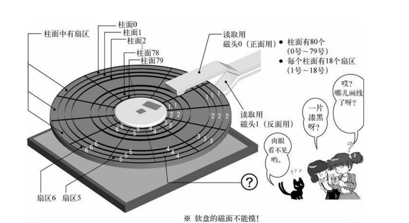
; select sector to read
mov ch,0 ; cylinder 0
mov cl,2 ; sector 2
mov dh,0 ; head 0
mov dl,0 ; driver A
mov al,1 ; read only 1 sector

; invoke bios to read
mov ah,2
int 0x13

; check error
jc error

floppy disk geometry

Add retry section

BIOS : reset disk system

Parameter
Register Value
AH 0x00
DL Driver number
Result
Register Value
CF Set on Error
AH return code
1
2
3
4
5
6
7
8
9
10
11
12
13
14
15
retry:
; try to read
mov ah,0x02
mov al,1
mov bx,0
mov dl,0x00
int 0x13
jnc fin ;if success halt the machine
add si, 1 ; fail time += 1
cmp si,5 ; maximum fail time is 5
jc error ; the author make a mistake here, this should be jc rather than jae
mov ah,0x00 ; reset floppy disk
mov dl,0x00
int 0x13
jmp retry

Read more sectors

1
2
cl += 1
es:bx += 512
1
2
3
4
5
6
7
next:
mov ax,es
add ax,0x20 ;add 512
mov es,ax
add cl,1
cmp cl,18 ; read 18 sectors
jbe readloop

Read more cylinders

1
2
3
4
5
6
7
8
9
10
11
12
13
14
15
16
17
next:
mov ax,es
add ax,0x20
mov es,ax
add cl,1
cmp cl,18
jbe readloop
; if finish reading one surface(18 sector), read the other
mov cl,1
add dh,1
cmp dh,2
jb readloop
; next cylinder
mov dh,0
add ch, 1 ; cylinder number += 1
cmp ch,CYLS ; const CYLS = 10
jb readloop

Start Develop our OS

when saving files into a floppy disk

  • file name is saved at 0x002600
  • file content is saved at 0x004200

BIOS int 0x10

Function Function code Parameters Return
Set video mode AH=0x00 AL=video mode AL=video mode flag
1
2
3
4
5
6
7
8
9
10
11
12
; source of haribote.sys

;code should start at memory 0x8000 + 0x4200 = 0xc200
org 0xc200 ; originate from 0xc200

mov al,0x13 ; use vga video card, 320x200x8 bit color
mov ah,0x00
int 0x10

fin:
hlt
jmp fin
1
2
3
4
; source of ipt.nas
; add two line after `next` section
mov [0x0ff0],ch ;save number of cylinder read to memory
jmp 0xc200 ;execute code of haribote.sys

blank screen in video mode

Preparing for 32-bit mode

switching from real mode to protected mode

16-bit mode machine code differs from 32-bit mode machine code !

So No BIOS function in 32-bit mode, since BIOS is written in 16-bit assembly !

Use BIOS to get some information before entrying protected mode

1
2
3
4
5
6
7
8
9
10
11
12
13
14
15
16
17
18
19
20
21
22
23
24
25
26
27
; source of haribote.nas

;boot info location
CYLS equ 0x0ff0 ; cylinder read
LEDS equ 0x0ff1 ; keyboard led status
VMODE equ 0x0ff2 ; video mode
SCRNX equ 0x0ff4 ; screen resolution x
SCRNY equ 0x0ff6 ; screen resolution y
VRAM equ 0x0ff8 ; start of video RAM

org 0xc200
mov al,0x13 ; set video mode
mov ah,0x00
int 0x10
mov byte [VMODE], 8
mov word [SCRNX], 320
mov word [SCRNY], 200
mov dword [VRAM], 0x000a0000

;use bios to get keyboard led status
mov ah,0x02
int 0x16
mov [LEDS],al

fin:
hlt
jmp fin

其实VRAM分布在内存分布图上好几个不同的地方。这是因为,不同画

面模式的像素数也不一样。当画面模式为〇×时使用这个VRAM;而画

面模式为◇△时可能使用那个VRAM,像这样,不同画面模式可以使用

的内存也不一样。

在INT 0x10的说明的最后写着,这种画面模式下“VRAM是0xa0000~0xaffff的64KB

Using the C language

Before using the C, we still need to do some job in real mode, but the code in asmhead.nas will be explicated later

1
2
3
4
5
6
// source of bootpack.c
void HariMain(void){
fin:
//hlt here
goto fin;
}

the author use a bounch of customized tools to do the compilation and linking

1
2
3
4
5
6
7
8
9
10
11
12
13
14
15
16
17
18
19
20
21
22
23
24
$ file bootpack.obj
bootpack.obj: Intel 80386 COFF object file, not stripped, 3 sections, symbol offset=0x91, 9 symbols
$ objdump -d bootpack.obj
bootpack.obj: file format COFF-i386


Disassembly of section .text:

00000000 _HariMain:
0: 55 pushl %ebp
1: 89 e5 movl %esp, %ebp
3: eb fe jmp -2 <_HariMain+0x3>
$ objdump -d halt.obj

halt.obj: file format Mach-O 32-bit i386


Disassembly of section __TEXT,__text:

00000000 _main:
0: 55 pushl %ebp
1: 89 e5 movl %esp, %ebp
3: e9 00 00 00 00 jmp 0 <_main+0x8>
8: e9 fb ff ff ff jmp -5 <_main+0x8>
1
2
3
4
5
% cc1.exe # c compiler (C source code -> GNU assembly code)
% gas2nask.exe # translator (GNU assembly -> nasm assembly)
% nask.exe # assembler (nasm assembly -> machine code)
% obi2bim.exe # linker
% bim2hrb.exe # format transferring, can be transformed into windows,linux and hariboteOS

Add a hlt function

1
2
3
4
5
6
7
8
9
10
11
; source of naskfunc.nas
[FORMAT "WCOFF"]
[BITS 32]
[FILE "naskfunc.nas"]

global _io_hlt
[SECTION .text]

_io_hlt:
hlt
ret
1
2
3
4
5
6
7
//bootpack.c
void io_hlt(void);
void HariMain(void){
fin:
io_hlt();
goto fin;
}

You see that we link c program and assembly program together