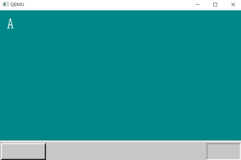
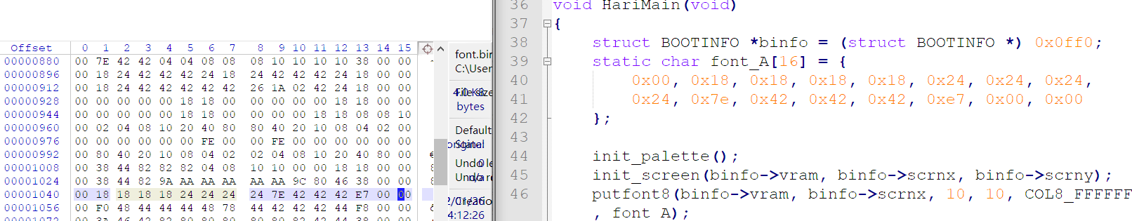
voidputfont8(char * vram , int xsize, int x , int y , char c , char * font ){ //c stand for color int i ; char * p , d ; //16 bytes per character for (i = 0 ; i < 16 ; i++){ p = vram + (y+i)*xsize + x ; //2D to 1D, (x,y) indicate the position d = font[i] ; //get the byte //check the byte bit by bit, if non-zero, fill it if ((d & 0x80) != 0) { p[0] = c; } if ((d & 0x40) != 0) { p[1] = c; } if ((d & 0x20) != 0) { p[2] = c; } if ((d & 0x10) != 0) { p[3] = c; } if ((d & 0x08) != 0) { p[4] = c; } if ((d & 0x04) != 0) { p[5] = c; } if ((d & 0x02) != 0) { p[6] = c; } if ((d & 0x01) != 0) { p[7] = c; } } }
It will be troublesome for us to make the font one by one, so we use a external font family and link it with out OS
voidputfonts8_asc(char * vram , int xsize , int x , int y , char c , unsignedchar * s){ externchar hankaku [4096]; for (; *s != '\0' ; s++){ putfont8(vram ,xsize , x, y, c , hankaku+ (*s) * 16); } }
Use sprintf for debug purpose
As declared by the auther, this version is sprintf is OS independent
voidinit_mouse_cursor8(char *mouse, char bc) /* prepare cursor buffer(16×16), write into mouse */ { staticchar cursor[16][16] = { "**************..", "*OOOOOOOOOOO*...", "*OOOOOOOOOO*....", "*OOOOOOOOO*.....", "*OOOOOOOO*......", "*OOOOOOO*.......", "*OOOOOOO*.......", "*OOOOOOOO*......", "*OOOO**OOO*.....", "*OOO*..*OOO*....", "*OO*....*OOO*...", "*O*......*OOO*..", "**........*OOO*.", "*..........*OOO*", "............*OO*", ".............***" }; int x, y; for (y = 0; y < 16; y++) { for (x = 0; x < 16; x++) { if (cursor[y][x] == '*') { mouse[y * 16 + x] = COL8_000000; } if (cursor[y][x] == 'O') { mouse[y * 16 + x] = COL8_FFFFFF; } if (cursor[y][x] == '.') { mouse[y * 16 + x] = bc; } } } return; } //bc stand for background color
voidputblock8_8(char * vram , int vxsize , int pxsize , int pysize , int px0,int py0, char * buf , int bxszie ){ // vram : video memory // vxsize : screen x resolution // pxsize : picture x size // pysize : picture y size // (px0 , py0) : position // buf : picture data // bxsize : picture data x size, usually equals to pxsize int x , y ; for ( y = 0 ; y < pysize ; y++){ for (x = 0 ; x < pxsize ; x++){ vram[(py0+y) * vxszie + (px0+x)] = buf[y * bxsize + x]; } } }
GDT and IDT
Segments management
How to describe a segment ?
64 bits segment discriptor
Segment size
Start address of the segment
Accessibility of the segment
However, the segment base register is still 16 bit, we need a external data structure to store these infomation
The value in DS(segment register) is called segment selector, funtions like the index of an array(GDT)
For some historical reason, the lowest 3 bits of DS is unusable, so the size of GDT is (2**13) * 64 bits
GDT(Global segment Desciptor Table)
Stored in memory
The start address of GDT and size limitation is stored in GDTR (global discriptor table register)
//GDT entry structSEGMENT_DESCRIPTOR{ short limit_low; short base_low ; char base_mid ; char access_right ; char limit_high ; char base_high ;
//segment base addr = catenate(base_high , base_mid , base_low) //why divide 4 bytes address into 3 parts? //For back compatibility of 80286
//segment size limit = catenate(limit_high & 0xffff , limit_low) //why size limit is only 20 bits ? //12 bits for access infomation //So the biggest size is 1 MB ? //If G_bit in accessInfo is turned on, the limitSize will be interpreted as number of pages // max_seg_size = 1MB * 4KB(page size) = 4G
//segment access right // limit_high & 0xffff0000 is called extended access right bits, used as xx00 // the first bit is G_bit // the second bit is used to indicate protected mode or real mode(only for 80286, not for BIOS) // access_right : // 0x00 : not allocated // 0x92 : OS only, rw_ // 0x9a : OS only, r_x // 0xf2 : User seg , rw_ // 0xfa : User seg , r_x // OS only (ring0) , User (ring3) };
//IDT entry structGATE_DESCRIPTOR{ short offset_low ; short selector ; char dw_count ; char access_right ; short offset_high ; };
//the struct format is required by CPU manufacturer, please read the manual
voidinit_gdtidt(void){ //arbitrarily pick two free address region in memory for GDT and IDT structSEGMENT_DESCRIPTOR * gdt = (struct SEGMENT_DESCRIPTOR*) 0x00270000 ; structGATE_DESCRIPTOR * idt = (struct GATE_DESCRIPTOR) 0x0026f800 ; int i ; //init GDT for (i = 0 ; i < 8192 ; i++){ set_segmdesc(gdt + i , 0 , 0 , 0); } //set entry 1 and 2 set_segmdesc(gdt + 1 ,0xffffffff,0x00000000,0x4092); //CPU access segment ,4G set_segmdesc(gdt + 2 ,0x0007ffff,0x00280000,0x409a); // bootpack access segment, 512 bytes //load GDT address into GDTR load_gdtr(0xffff,0x00270000); //init IDT for (i = 0 ; i < 256 ; i++){ set_gatedesc(idt + i , 0 , 0, 0); } load_idtr(0x7ff , 0x0026f800) ; return ; }
/* limit : size upper bound base : base address ar : access right */